Auxilliary input for Grundig AD182 series head units.
What's this all about ? :
This tutorial describes how to add an auxilliary line level input for mp3 players or other line level sources to the Grundig AD182 series head units, which are the original stereo's supplied by FIAT in the lovely Bravo, Brava and Marea. The higher spec head units such as the AD182H2 or H3 are actually quite decent, and as they fit and complement the dash, its a shame to pull them out. Also, they have a permanent clock on the display when switched off or on, which you would miss on other head units. Also, they have connections for a phone kit, so you can use the radio speakers for the phone. And several other nice features. Excellent !.
How it works :
The higher spec FIAT grundig radio's have an auxilliary connector at the rear for adding a grundig CD changer. There is also a connector for a steering wheel remote control and mobile phone car kit interface, and a 4 channel line level out for external amplifiers. The CD changer interface has a left and right audio input, a single BUS data line for passing commands to/from the CD changer, and power for the changer unit. On most head units such as sony's etc, the CD changer interface has two or more data/control lines, and audio inputs, e.g. the sony unilink bus. The head unit communicates with the changer unit over the data bus, and the CD audio is fed in through the left and right audio inputs. Normally, to get the radio to switch over to the CD changer, the changer unit must tell the head unit that it is present on the bus, only then will the radio allow the audio inputs to work. To get these to work as an aux input, the radio needs to see a device on the bus. This can be achieved using an adapter, which fools the radio into thinking there is a changer, but it actually has to send the track and time info etc. However, the cost of an adapter can sometimes be more than the radio is worth, in which case a radio with a dedicated aux input might be better, but these are not really that common.
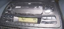
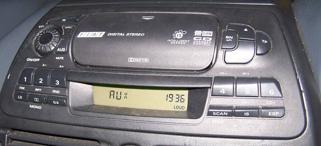
On the grundig radio's however, it suffices to pull the single bus line low permanently. No data exchange is necessary. It seems this may have been intentional by grundig as an undocumented feature (or maybe a bug !), as the display changes to "AUX" as if it were actually an auxilliary input, and the "SRC" button will switch between the auxilliary input, radio and tape also.
What you need :
- you will need a working AD182H2/3 head unit
- The code for the radio, if it is locked.
- suitable tools to remove the radio (feeler guage blades or other
long, flat thin implements), and cut and strip wires (a snips or
stanley knife begod !)
- about a metre of screened twin audio cable (or old headphone cable)
- 3.5mm stereo plug (or old headphone cable with plug)
- CD changer cable with blue connector. (can get by without it if you can solder)
- 1 or more 100 ohm resistors. (see text)
- Soldering Iron and solder
- Insulating tape or small diameter heatshrink tubing.
- Some electrical or electronics knowledge helps, or a knowledgeable friend.
Removing the head unit (important !) :
If you want to completely disconnect the radio, make sure that you have the code, as you will need it when you power it back up again. If you cannot find the code, there is a possibility that the code might have been turned off, and you can check by looking at the setting in the EXPERT function (hold down the EXP button for more than 3 seconds until the display changes to >>EXPERT<<. Then scroll down until you see CODE or SAFE in the display. SAFE means the CODE is activated, and CODE means it is deactivated. If it's deactivated, you can disconnect the radio completely. If it's activated, you may be able to continue provided you don't remove the connector plug A from the radio (see pic below). This can be tricky though, because Murphy's law means the wires are never long enough to allow easy access !.
Also, it can be difficult to remove the radio without resorting to butchery, but please please please don't do that !. If you read the ICE faq at the bravo guide you should fare better..
the BOO ICE guide
If the code is lost or wrong, the code can be read from the radio, or decoded from the serial number on the side.
How to connect it all up :
To use your mp3 player or other audio source, you need to get a plug that will take a line output, or a headphone output from it. This will usually be a 3.5 mm stereo jack plug, so it would usually suffice to cut the cable off an old pair of headphones, complete with plug, like I have done (see photo's). Leave enough cable to go from the back of the radio down to a suitable location, e.g. below the cigarrette lighter/ash tray, or to a proper mounting cradle if you have one. I just leave my mp3 player in the tray below the console, and have enough cable so i can pull it close to me to use it.
Then, you need to connect this into the back of the radio. you could use the connector that comes with the CD changer cable, these were fitted as standard to early MK1 bravo/a's, and can sometimes be obtained from a scrappers, or purchased from FIAT. Or, you could just solder the wires directly to the pins. The pins are a bit small and close together though, and thus tricky to solder.
Here is the pinout of the CD changer part of the auxilliary connector on the back of the head unit :
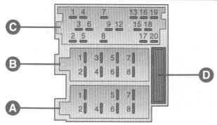
The pins on the connectors are as
follows (note this pinout is also shown in the FIAT user manuals) :
As can be seen, the connector also has connections for an external amplifier (line outputs), car phone kit and steering wheel remote. All these goodies on an OEM stereo !
Using a cd changer cable :
If you can spare the original grundig CD changer cable, cut off the blue connector at the end, and leave maybe 4 inches of the cable. Pull off the outer insulation to leave the single wires. The audio inputs on pins 19 and 20 will be a seperate screened cable inside the main cable. Pull the outer insulation and screen foil off these too. This should leave you with enough length of wires to connect the cable..
| Connector C (top of radio) |
Connector
B (speakers) |
Connector
A (power and auxilliary's) |
|
|
|
As can be seen, the connector also has connections for an external amplifier (line outputs), car phone kit and steering wheel remote. All these goodies on an OEM stereo !
Using a cd changer cable :
If you can spare the original grundig CD changer cable, cut off the blue connector at the end, and leave maybe 4 inches of the cable. Pull off the outer insulation to leave the single wires. The audio inputs on pins 19 and 20 will be a seperate screened cable inside the main cable. Pull the outer insulation and screen foil off these too. This should leave you with enough length of wires to connect the cable..
The above diagram shows the blue
connector plug on the left, and the wire colours. The red and white
wires (pins 20 and 19) are the right and left audio inputs
respectively, as shown in the table above. You can use an old headphone
cable complete with the plug to connect your mp3 player, but bear in
mind that this cable is usually cheap and not properly screened, and
will therefore be more affected by RF from mobile phone's etc,
especially if you will be using a car kit nearby. It would be better to
get a bit of proper screened twin audio cable, and put a plug on the
other end. As shown above, connect the screened pair to the left
(white) and right (red) inputs, and the cable screen (usually bare
copper - twist this together tightly) to the thicker black wire from
pin 18 (audio earth).
Now connect a low value resistor (any value up to 1 Kohm should work) between the green wire on pin 13 (BUS) and the black wire on pin 15 (BUS earth) as shown above. This will ground the BUS line, and allow the unit to switch to the AUX mode. Note that you could just short the BUS line to the earth wire if you had no resistor, but I cannot guarantee that this will not damage the head unit, as its not a good idea to short data lines directly to earth (and no, I have not tried it !).
A 100 ohm resistor has brown, black, brown and gold or silver coloured bands on its body. If you get them from Maplins or other electronics places then just ask for 100 ohm resistors.
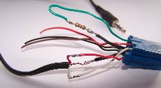
It is better to solder the wires together, but if you cannot then just remove about 10mm of the insulation from each wire and twist them together tightly, and fold over. then insulate the connections with insulating tape or better still use heatshrink tubing (remember to slide it on the wires first !). For the resistor, wrap the strands of wire around the resistor's leads and fold the leads to prevent the wires pulling off. Insulate these connections as well.
What if I don't have the blue plug ? :
Then you will have to solder the wires and resistor directly into the back of the head unit socket, using the pinouts shown above. You may have to heat and tin the pins with a bit of solder first, as they will not solder easily first time. Be careful not to overheat the pins, as they will melt the plastic socket and possibly come out of the PCB behind. Also, it will be a bit more awkward to refit the radio afterwards. Alternatively, you could get some small (speaker size) push on spade crimp connectors, but the smallest ones are still not really small enough and will possibly short each other unless insulated with insulating tape.
Testing and use :
Before you refit the radio, test the cable to make sure it works. Plug the blue connector into the top socket (socket A) on the right hand side. Also, if there were yellow and green plugs also joined to it, use them as well. Reconnect the power and speaker connections and turn on the radio (enter the code if necessary). The radio should come on as normal, and if you press the "SRC" button, the radio display should change to AUX after a second or two. Now connect the 3.5 mm plug (or whatever plug you required) into the "Line Out" socket on the mp3 player, or the headphone socket if it does not have a line out. Turn it on, and you should hear the sound through the speakers. Note that if you use a headphone socket on the mp3 player, you may have to turn the volume up a good bit higher than normal to match the normal volume level on the head unit. This is because the headphone output is a lower impedance output to drive the headphones, and thus does not have as high a voltage output. A line level output should be fine though.
If all works well, drop your cable down to where you want it, you should be able to drop it down behind the radio at the left hand side of the center console and out at the ashtray. Then reconnect and carefully refit the radio, it should not have to be forced back in too much, check for the cables getting trapped or caught behind if it does.
Here the head unit is in AUX mode.. (click for larger image)
Problems :
Oh dear...
If you find that the radio does not switch to AUX mode, check the BUS resistor connections, and make sure it has a low enough value (up to 1 Kilohm works for me). Are you holding the "SRC" button down long enough ?.
If the sound quality is poor or distorted, check the BASS and TREBLE settings on the radio in case they have gone outrageous. If ok, then there is a possibilty that if you are using the headphone socket of your mp3 player or whatever, that its headphone amplifier does not like the high impedance of the audio inputs, which are relatively high compared to headphones. To correct this, you may need to load the audio inputs down with two low value resistors, to simulate the headphones. something around 100 ohms or less should do the trick, but make sure the resistors have the same value. Connect a resistor from each audio input to earth (gnd) at the blue connector as shown below..
If using a headphone socket and the audio level is still too low, even with the head unit volume at max, you may need to amplify the outputs using a stereo preamp before feeding to the head unit. A small preamp may be obtained at boy racer shops (sorry, i meant auto accessory or ICE shops :-) ), or electronics places like Maplins. If possible, the preamp should have a gain preset so you can set the input level to cloesely match the normal headphone and radio volume levels.
If you have any further questions please email me at : owenoreilly at utvinternet dot com
Enjoy !!
This page last updated 20/02/2006
Now connect a low value resistor (any value up to 1 Kohm should work) between the green wire on pin 13 (BUS) and the black wire on pin 15 (BUS earth) as shown above. This will ground the BUS line, and allow the unit to switch to the AUX mode. Note that you could just short the BUS line to the earth wire if you had no resistor, but I cannot guarantee that this will not damage the head unit, as its not a good idea to short data lines directly to earth (and no, I have not tried it !).
A 100 ohm resistor has brown, black, brown and gold or silver coloured bands on its body. If you get them from Maplins or other electronics places then just ask for 100 ohm resistors.
It is better to solder the wires together, but if you cannot then just remove about 10mm of the insulation from each wire and twist them together tightly, and fold over. then insulate the connections with insulating tape or better still use heatshrink tubing (remember to slide it on the wires first !). For the resistor, wrap the strands of wire around the resistor's leads and fold the leads to prevent the wires pulling off. Insulate these connections as well.
You should end up with something like
this. Note that I have shown without insulation for clarity. (click
image for larger version)

What if I don't have the blue plug ? :
Then you will have to solder the wires and resistor directly into the back of the head unit socket, using the pinouts shown above. You may have to heat and tin the pins with a bit of solder first, as they will not solder easily first time. Be careful not to overheat the pins, as they will melt the plastic socket and possibly come out of the PCB behind. Also, it will be a bit more awkward to refit the radio afterwards. Alternatively, you could get some small (speaker size) push on spade crimp connectors, but the smallest ones are still not really small enough and will possibly short each other unless insulated with insulating tape.
Testing and use :
Before you refit the radio, test the cable to make sure it works. Plug the blue connector into the top socket (socket A) on the right hand side. Also, if there were yellow and green plugs also joined to it, use them as well. Reconnect the power and speaker connections and turn on the radio (enter the code if necessary). The radio should come on as normal, and if you press the "SRC" button, the radio display should change to AUX after a second or two. Now connect the 3.5 mm plug (or whatever plug you required) into the "Line Out" socket on the mp3 player, or the headphone socket if it does not have a line out. Turn it on, and you should hear the sound through the speakers. Note that if you use a headphone socket on the mp3 player, you may have to turn the volume up a good bit higher than normal to match the normal volume level on the head unit. This is because the headphone output is a lower impedance output to drive the headphones, and thus does not have as high a voltage output. A line level output should be fine though.
If all works well, drop your cable down to where you want it, you should be able to drop it down behind the radio at the left hand side of the center console and out at the ashtray. Then reconnect and carefully refit the radio, it should not have to be forced back in too much, check for the cables getting trapped or caught behind if it does.
Here the head unit is in AUX mode.. (click for larger image)
!!!! Warning !!!!
- if you have to turn up your mp3 player volume, remember to turn it
down again before using the headphones. I can take no responsibility
for damaged hearing etc..
Problems :
Oh dear...
If you find that the radio does not switch to AUX mode, check the BUS resistor connections, and make sure it has a low enough value (up to 1 Kilohm works for me). Are you holding the "SRC" button down long enough ?.
If the sound quality is poor or distorted, check the BASS and TREBLE settings on the radio in case they have gone outrageous. If ok, then there is a possibilty that if you are using the headphone socket of your mp3 player or whatever, that its headphone amplifier does not like the high impedance of the audio inputs, which are relatively high compared to headphones. To correct this, you may need to load the audio inputs down with two low value resistors, to simulate the headphones. something around 100 ohms or less should do the trick, but make sure the resistors have the same value. Connect a resistor from each audio input to earth (gnd) at the blue connector as shown below..
If using a headphone socket and the audio level is still too low, even with the head unit volume at max, you may need to amplify the outputs using a stereo preamp before feeding to the head unit. A small preamp may be obtained at boy racer shops (sorry, i meant auto accessory or ICE shops :-) ), or electronics places like Maplins. If possible, the preamp should have a gain preset so you can set the input level to cloesely match the normal headphone and radio volume levels.
If you have any further questions please email me at : owenoreilly at utvinternet dot com
Enjoy !!