Electrical faults
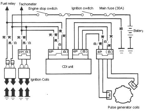
Explanation of diagram.
The pulse generator is inside the engine on the clutch side, the wire that comes
out the front of the clutch cover is the pulse generator wire. The pulse generator is
connected to the crankshaft, every time the crankshaft turns a pulse is generated and
sent to the CDI unit. Measure resistane of the pulse generator coils at the CDI unit
Pulse generator coil resistance: 450Ω-550Ω
The CDI unit relies on the pulse generator to tell it when to fire a spark plug.
It also controls the ignition advance.
_______________________________________________
Ignition advance for Bros 400 J/K
10° BTDC, "F" mark, at idle (1,200 rpm)
32° BTDC at 9,000 +/- 200 rpm, full advance
_____________________
Ignition advance for Bros 650 J/K
10° BTDC, "F" mark, at idle (1,200 )
31° BTDC at 7000 +/- 200 rpm, full advance
_______________________________________________
Firing order: Front-232°-rear-488°-front-
_______________________________________________
The primary circuit is the path an electrical current will take from B to A and B to C.
Primary circuit resistance: 2.2Ω-2.6Ω
Excessive primary circuit resistance can be caused by the wires going to the coils or
the coils themselves.
_______________________________________________
The secondry circuit it the path taken by the induced current in the coil, it will flow thru
HT wire A, spark plug A, the cylinder head, spark plug B, HT wire B and back into the coil.
Remove both spark plug caps and measesure the resistance from one cap to the other
Secondry circuit resistance including HT wires and caps: 30KΩ-36KΩ
Secondry circuit resistance, coil only: 20KΩ-25KΩ
_______________________________________________
With the key ignition switch on and the engine stop switch on "RUN", battery
voltage should come between A-D, B-D and C-D.
_______________________________________________
There is a second wire on the A and C connector pins, the second wire is for the
tachometer and the other second wire is for the fuel pump relay.
_______________________________________________
Battery
- YTX9-BS (CTX9-BS)(150mm length × 88mm width × 106mm height).
- Capacity: 12V, 8Ah
- Voltage that idicates fully charged battery: 13.0 - 13.2 V
- Voltage that idicates charging required: 12.3 V or less
- Charge current: 0.9 A
- Max. current leakage: 0.1 A
- Charge time: 5 h
_______________________________________________
The CDI unit is a capacitive discharge iginition unit with fully transistorised
ignition advance.
_______________________________________________
Tests
The spark test
- The spark test is dangerous.
- Do not touch the ignition system if you have a pace maker or a heart problem,
because there is a high risk of a high voltage electric shock.
- While performing the spark test, petrol vapours may escape from the engine,
which will cause an explsion if ignited by a spark, a naked flame or a cigarette.
- The Bros engine is unusual in that it has two spark plugs per cylinder.
- Put gearbox into neutral and switch engine off.
- To do the spark test on a front cylinder spark plug, remove both caps from rear cylinder
plugs to prevent this cylinder form firing
- Remove one spark plug from the front cylinder
- Fit this spark plug into it's cap and ground the plug by touching the plug outer against a
bare metal part of the engine.
- Ensure the other spark plug is fitted and connected
- Turn on ignition switch and turnengine stop switch to run and crank the engine to see if a
spark is present.
Note: The other spark plug in the cylinder may ignite the fuel witch might be dangerous.
- Repeat for other plugs
Causes of no spark
- Bad spark plug, wire or cap.
- Open circuit in primary, secondry or pulse generator circuits.
- Defective CDI unit or coil.
- Loose or corroded connector(s)
Causes of weak spark
- Bad spark plug, wire or cap
- Excessive primary, secondry or pulse generator circuit resistance.
- Loose or corroded connector(s).
- Weak coil or expired HT wires and caps.
- Weak voltage from battery
Check battery charging voltage:
- Remove seat
- Remove battery cover
- Measure battery voltage
- Check for loose or coroded terminals
- Start engine out doors
- The battery charging circuit actuates only when the engine speed is more
than 1200 rpm so you should ensure the idle speed is greater than this.
- Measure battery voltage again, if it is higher than before and climbing then
the charging circuit is probably OK.
Check battery leakage:
- Check for loose or coroded terminals
- With key ignition switch off.
- Disconnect cable from negative battery terminal
- Attach one lead of amp-meter to negative battery terminal and the other lead
to disconnceted negative cable.
- If current is greater than 0.1 Amp then there is a fault or short circuit somewhere.
Regulated voltage inspection
- Check for loose or coroded terminals
- Start engine and warm up outdoors
- Stop engine
- Connect volt meter to battery
- Start engine and gradually increase to 3000 rpm
- Battery voltage should stay between 13.5 V - 15.5 V

Ampere inspection
- Start engine and warm up outdoors
- Stop engine
- Remove seat cowling
- Check for loose or coroded terminals
- Remove main fuse from starter relay then re-connect connector.
- Attach voltmeter probes to main fuse terminals from underneath, push all the way in.
- Start engine and gradually increase to 3000 rpm
- Amperage should be around 0.5 A
Regulator rectifier

- 3 phase, full wave
- 3 pin connector block goes to generator inside engine (left side)
- 4 pin connector block contains two grounds and two positives
- Check for loose or coroded terminals
- The regulator/rectifier is a semiconductorized unit; use the specified tester.
If a different tester is used the the test results will be out of specification.
- You'll get a false reading if your finger touches the tester probe.
- On the battery charging line battery voltage should come.
- Note: the polarity of the ohm-meter effects the reading, positive probe on top row of
table and negitive probe on left coloum.
Also the applied measuring voltage will affect to reading so only use Honda tool.
Generator inspection (stator)(alternator)
- It is not neccesary to remove the generator coil to perform this test.
- Disconnect the 3 pin connector from the generator.
- Measure the resistance between each of the wires 0.1Ω - 1.0Ω (20°C)
- None of the wires should have continuity with ground