Info
4 stroke engine:
A stroke is a complete movement of the piston in one direction.
When the piston is at it's highest point it is said to be at top dead center (TDC).
When the piston is at it's lowest point it is said to be at bottom dead center (BDC).
There are four piston strokes in one complete cycle of the engine.
The crankshaft completes two revolutions in one complete engine cycle.
The cam shaft completes one revolution in one complete engine cycle.
The four strokes are as follows, starting at TDC on the exhaust stroke:
When setting the valve clearances the piston should be at TDC on the compression stroke.
Rotate the crankshaft counter clockwise and watch the valves opening and closing to find this point.
It should be 90° after the inlet valves close, use notch on flywheel to find exact position.
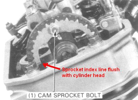
Also the index line on the cam sprocket should be flush with the top of the cylinder head at this point.
Also all the lobes on the camshaft should be facing down at this point.
Common faults:
Common mistakes made during cylinder head work:
Tools:
Parts you definitely require:
Parts you might require:
Job
Rear cylinder:
Front cylinder head:
Cylinder head inspection:
Valves:
| 400cc | 650cc | |
| IN Valve guide ID new | 5.500mm - 5.512mm | 5.500mm - 5.512mm |
| Ex Valve guide ID new | 5.500mm - 5.512mm | 6.6000mm - 6.615mm |
| IN Valve guide ID service limit | 5.54mm | 5.54mm |
| EX Valve guide ID service limit | 5.55mm | 6.65mm |
| IN Valve stem OD new | 5.475mm - 5.490mm | 5.475mm - 5.490mm |
| EX Valve stem OD new | 5.455mm - 5.470mm | 6.555mm - 6.570mm |
| IN Valve stem OD service limit | 5.47mm | 5.47mm |
| EX Valve stem OD service limit | 5.44mm | 6.54mm |
| IN Stem to guide clearance new | 0.010mm - 0.037mm | 0.010mm - 0.037mm |
| EX Stem to guide clearance new | 0.030mm - 0.057mm | 0.030mm - 0.06mm |
| IN Stem to guide clearance servicel limit | 0.07mm | 0.07mm |
| EX Stem to guide clearance servicel limit | 0.09mm | 0.09mm |
| IN/EX Valve seat width new | 0.9mm - 1.1mm | 0.9mm - 1.1mm |
| IN/EX Valve seat width service limit. | 1.5mm | 1.5mm |
| Inlet inner spring | Exhaust inner spring | Inlet outer spring | Exhaust outer spring | |
| 400cc | 35.7mm | 38.7mm | 44.5mm | 42.5mm |
| 650cc | 36.8mm | 37.5mm | 40.6mm | 41.3mm |
Camshaft:
| Inlet new | Inlet servicel limit | Exhaust new | Exhaust service limit | |
| 400 | 37.268mm | 37.19mm | 37.685mm | 37.60mm |
| 600 | 38.060mm | 37.98mm | 38.082mm | 38.00mm |
Cylinder head block
Cylinder inspection
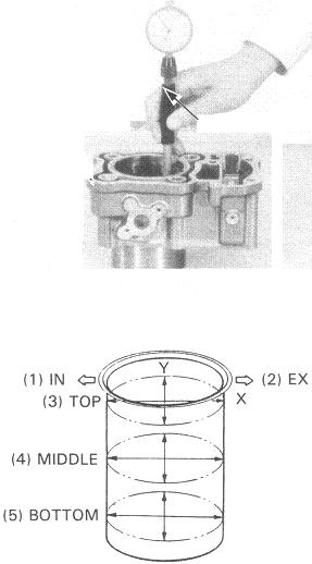
| 400cc | 650cc | |
| Cylinder ID, new | 64.000mm - 64.015mm | 79.000mm - 79.015mm |
| Cylinder ID, service limit | 64.1mm | 79.1mm |
| Piston to cylinder clearance, new | 0.010mm - 0.055mm | 0.010mm - 0.055mm |
| Piston to cylinder clearance, service limit | 0.1mm | 0.1mm |
| Taper service limit | 0.05mm | 0.05mm |
| Out of round, service limit | 0.05mm | 0.05mm |
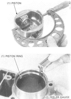
Piston and rings inspection
Notes:
| 400cc | 650cc | |
| Piston OD, N | 63.96mm - 63.99mm | 78.96mm - 78.99mm |
| Piston OD, SL | 63.9mm | 78.9mm |
| Piston pin OD, N | 14.994mm - 15.000mm | 19.994mm - 20.000mm |
| Piston pin OD, SL | 14.98mm | 19.98mm |
| Bore for piston pin, N | 15.002mm - 15.008mm | 20.002mm - 20.008mm |
| Bore for piston pin, SL | 15.05mm | 20.05mm |
| "Piston pin bore" to "piston pin" clearance, N | 0.002mm - 0.014mm | 0.002mm - 0.014mm |
| "Piston pin bore" to "piston pin" clearance, SL | 0.04mm | 0.04mm |
| "Piston pin" to "connecting rod" clearance, N | 0.016mm - 0.040mm | 0.016mm - 0.040mm |
| "Piston pin" to "connecting rod" clearance, SL | 0.06mm | 0.06mm |
Piston rings
| 400cc | 650cc | |
| "Ring" to "ring groove" clearance, top, N | 0.025mm - 0.060mm | 0.025mm - 0.055mm |
| "Ring" to "ring groove" clearance, top, SL | 0.08mm | 0.08mm |
| "Ring" to "ring groove" clearance, second, N | 0.015mm - 0.045mm | 0.015mm - 0.045mm |
| "Ring" to "ring groove" clearance, second, SL | 0.06mm | 0.06mm |
| Ring end gap, top, N | 0.2mm - 0.35mm | 0.2mm - 0.35mm |
| Ring end gap, top, SL | 0.5mm | 0.5mm |
| Ring end gap, second, N | 0.35mm - 0.50mm | 0.35mm - 0.50mm |
| Ring end gap, second, SL | 0.7mm | 0.7mm |
| Ring end gap, oil, N | 0.2mm - 0.7mm | 0.2mm - 0.8mm |
| Ring end gap, oil, SL | 0.9mm | 1mm |
Cam oil feed pipe (chrome)
Re-assembly
Re-assembly is essentially the reverse order of disassembly.
Camshaft installation, valve timing.
The front and rear cam shafts are different, do not
confuse them.
There is an index line on the cam sprockets, when the
flywheel FT or RT mark is aligned, the index line on the
appropriate sprocket should be flush with the top of the
cylinder head.
Usually when all the cam lobes are facing down, all
the rocker arms will have a small amount of jog in them.
______________________________________________________
Front camshaft only.
Turn the crankshaft counter clockwise and align the RT
mark on the flywheel with the index mark on the timing hole.
Make sure the REAR cam lobes are all facing UP. If they are
not, turn the crankshaft counter clockwise one revolution so
that the REAR cam lobes are all facing UP. (NOTE: This is the
valve overlap position.)
 Continue turning the crankshaft counter clockwise (128°) until
the FT mark on the flywheel aligns with the index mark on
the timing hole (approx. 3/8 turn).
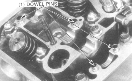
Install any necessary dowel pins.
Grease cam lobes and journals.
Install the camshaft in the cylinder head through the cam chain
and install the cam sprocket on the camshaft.
With the cam lobes all facing down, align the timing marks
(index lines) on the cam sprocket with the top of the cylinder
head.
Place the cam chain on the sprocket.
Install the cam sprocket on the camshaft flange and recheck
that the timing marks (index lines) align with the top of the
cylinder head.
Inspect valve clearance.
Align the cam sprocket bolt holes in the cam sprocket and
camshaft, install and tighten the cam sprocket bolt.
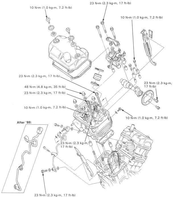
TORQUE: 23 Nm.
Install the holder, oil plate, 8 mm bolts, 8 mm nut and 6 mm
bolts.
TORQUE:
8 mm bolt: 23 Nm
8 mm nut: 23 Nm
6 mm bolt: 10 Nm
Turn the crankshaft counter clockwise 360° and install the
other sprocket bolt.
Install the end holder.
CAUTION
Note the direction of the camshaft end holder, install the flat
surface on the holder facing in.
______________________________________________________
Rear camshaft only
Turn the crankshaft counter clockwise and align the FT
mark on the flywheel with the index mark on the timing hole.
Make sure the FRONT cam lobes are all facing down. If they
are not, turn the crankshaft counterclockwise one revolution
so that the FRONT cam lobes are all facing down.
Continue turning the crankshaft counter clockwise (232°) until
the RT mark on the flywheel aligns with the index mark on
the timing hole (approx. 5/8 turn).
Place the camshaft into the correct position with the cam lobes all
facing down.
Install the cam sprocket and camshaft holders using the same
procedure as for the front cylinder.
Inspect valve clearance.
______________________________________________________
Front and rear cam shafts
Turn the crankshaft counter clockwise and align the FT
mark on the flywheel with the index mark on the timing hole.
Install the front camshaft with all the cam lobes facing DOWN.
Align the index marks on the cam sprocket with the top of the
cylinder head.
Continue turning the crankshaft counter clockwise (232°) until
the RT mark of the flywheel aligns with the index mark on
the timing hole (approx. 5/8 turn).
Install the rear camshaft with all the cam lobes facing DOWN.
Align the index lines on the cam sprocket with the top of the
cylinder head
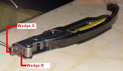
Remove the 2mm pins holding the tensioner wedges.
Note:
Be careful not to let the 2mm pin fall into the crankcase.
Do not forget to remove the 2mm pin.
Inspect valve clearance.
Double check valve timing and valve clearance.
________________________________________________________________________________