Class Diagrams
Pre-requisite knowledge:
Definition: domain: the world of the user community.
Definition: instance: a particular instance of a class, as in bigRectangle and smallRectangle may each be instances of the class Rectangle
Definition: object: same as instance above.
Definition: to constrain:
to force physically, by strong persuasion
or pressurising; to compel; to oblige; to keep within close bounds; to confine;
to reduce a result in response to limited resources
Definition: constraint:
that which constrains (see definition of to constrain above).
1. Introduction:
The class diagram is central within object-oriented methods.
As we'll see later:
Although a class diagram is called a class diagram, it actually shows the relationships between instances of the classes shown.
The advanced concepts are used less often. 90% of the time we stick with 10% of the available range of syntax; most projects don't need any more than that, give or take.
A class diagram describes the types of objects in the system and the various kinds of STATIC relationships that exist among them.
Among these relationships, we consider, principally, two:
Associations (for example: a customer may order a number of books, shown by a line connecting two classes - see diagram below)
Subtypes (for example: a lecturer is a kind of person), which can alternatively be expressed as the supertype being a generalisation of the subtypes. Shown by a line terminated by a white triangle - see first diagram below)
Class diagrams also show the attributes and operations (collectively called features) of a class and other constraints that apply to the way objects are connected.
The fact that there are two principal types of relationships: association and subtype, or its opposite, generalisation, can be remembered by ras/rag (well, as a memory aid, it works for me anyway!). The diagram a few paragraph below illustrates all the points discussed above.
Self-assessment: what do the following key words mean?
relationships, associations, subtypes (otherwise known as generalisation), attributes, operations, features, constraints.
2. Perspectives:
There are three perspectives you can use in drawing class diagrams, or indeed any model, but this breakdown is most noticeable in connection with class diagrams.
Conceptual:
You draw a diagram that represents the concepts in the domain under study. These concepts will relate to the classes that implement them, but not necessarily with any direct mapping. The diagram is drawn with little regard for the software that might implement it. For those on a second or third reading through these notes: For the conceptual perspective, in a rectangle representing a class, you show in an upper panel the name of the class and in the lower panel a natural language description of the responsibilities of the class.
Specification:
Now we’re looking at software but we’re looking at the interfaces of the software, not the implementation. Indeed, the key to effective OO programming is to program to a class’s interface, thereby treating the class as a sort-of black box. The word type may be used to talk about an interface of a class. For those on a second or third reading through these notes: For the specification perspective, in a rectangle representing a class, you show in the upper panel the name of the class, a middle panel empty of attributes, and a lower panel showing the names of the public methods together with their argument types and return types. You don't show attributes, since they should always be private, and part of the implementation of the class. (An example of this sort of thing might be a Rectangle class. Does each Rectangle object just know its length and breadth and calculate its own area when needed from its knowledge of its own length and breadth or alternatively, does it keep a note of its length, breadth and area at all times. It's precisely this soft of thing that is NOT, repeat NOT part of the specification perspective. We're only concerned with the outward behaviour of Rectangle objects, NOT how they achieve that behaviour. That's their business, so to speak, and doesn't get revealed until the implementation perspective. See the notes on the Rectangle class elsewhere on this web site.)
Implementation:
The implementation is laid bare; now we're into white box stuff. For those on a second or third reading through these notes: For the implementation perspective, in a rectangle representing a class, you show in the upper panel the name of the class, a middle panel showing the attributes, and a lower panel showing the names of both the public methods and private methods together with their argument types and return types. (Don't, necessarily bother showing the setters and getters of each attribute, since they can be taken for granted.)
Many modellers do not take care to get their perspectives sorted out when they’re drawing. This doesn’t matter too much between the conceptual and specification perspective; however it’s very important to separate the specification and implementation perspective. (Memory aid: cs | i )
The conceptual perspective does not involve software, just business/domain logic and reasoning; the other perspectives do involve notions to do with software.
My mnemonic, for what it's worth for Conceptual, Specification, Implementation is Crime Scene Investigators.
3. Fundamental Notation of class diagrams:
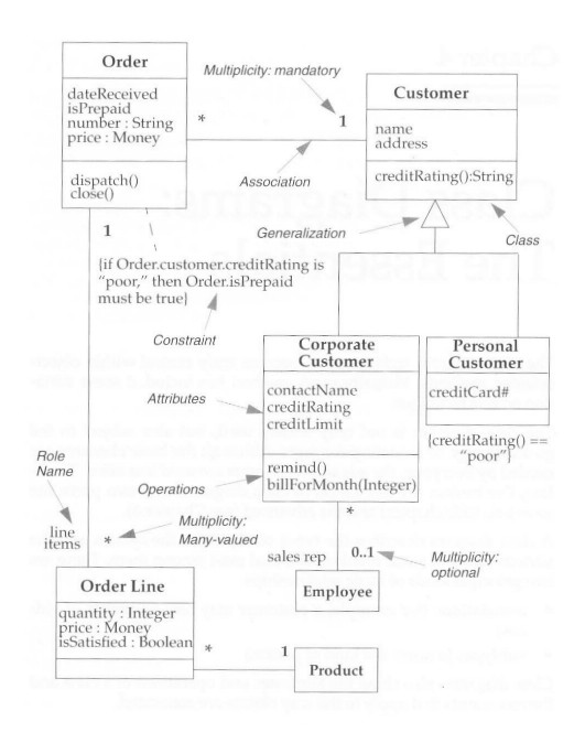
Consider the following diagram which is (contrary to the advice giving above) not quite drawn to any particular perspective. However, insofar as it shows attributes, it's tending more to be drawn from the implementation perspective.
We see a number of rectangles, seven in all, each of which represents a class. Most class boxes have three panels, representing name, attributes and behaviours. If there are no panels in the box, as for Employee and Product, then the text in the box represents the name of the class. Note that in some cases the return type of the method implementing a behaviour is shown after a colon (:) symbol. This notation is also used to show the type of an attribute. The subtype relationship is shown as is the association relationship. Associations typically have multiplicities on them, such as * representing none or more, 1 representing just one.
One association has a role name on it, sales rep (please search the diagram for it - it might incidentally have been better named salesRep), showing the role that an employee object is playing in regard to the association with Corporate Customer. Constraints are shown in curly brackets. They can be written in a natural language such as English, or in structured natural language or in OCL (object constraint language). They do what their name suggest, in other words they indicate constraints such as all personal customers having a poor credit rating, simply because the company neither keeps nor seeks any information about them in regard to them in regard to their likelihood of paying; they are made to pay before they get the goods!
We can also use the label salesRep for the role name in the diagram above. This notation involves capitalising the first letter of each word (except the first), and leaving no spaces between words. It's a notation familiar to most programmers.
It's worth noting that there is no essential difference between association and attribute. For example, we could simply have made the Employee that may serve as sales rep to a Corporate customer an attribute of Corporate Customer. So we'd have in Corporate Customer the following attributes:
contactName:String[1]
creditRating:String[1]
creditLimit:Money[1]
salesRep:Employee[0..1]
When an attribute is represented as an association, the attribute name becomes the role name.
Notice that in the above list of attributes, we've fleshed things out a little to show the types of the attributes and their multiplicities. In the diagram, some of the detail was suppressed, perhaps in the interests of simplicity. We see that multiplicities apply as much to attributes as they do to associations.
Associations represent relationships between instances of classes, in other words objects, not classes. Thus we have ideas such as a person works for a company; a company has a number of offices). You've got to remember that although a class diagram is called a class diagram, it actually shows the relationships between instances of the classes shown.
Some of the UML syntax rules about how to name attributes and operations can be appreciated from the diagram above. For example we have:
creditRating( ) : String
price: Money
isPrepaid
In each case the type follows the name, with colons separating them.
Clearly isPrepaid is of type boolean and so could have been written as
isPrepaid : boolean
But why clutter the diagram with stating that it's boolean when the name itself implied boolean? A judgement must be made as to what to put into a class diagram and what to leave for granted.
Attributes and associations can be fully dressed or in a partial state of undress on a class diagrams. The general rule is not to overcomplicate or be over-fussy. See sections 7 and 8 below for full details of attribute and operation syntax.
Discussion Question:
Given that we can seemingly think of an association as an attribute and vice versa, under what circumstances might it be best to think one way or the other. In other words when should we use the idea of attribute and when should we use the idea of association?
4. More on Perspective:
Conceptual Perspective:
From this perspective, associations represent domain-related relationships between instances of domain-related classes. These domain-related classes may not be the classes that actually implement the system in Java or some other language. The diagram indicates that an Order has to come from a single Customer and that a Customer may make several Orders over time. Each of these Orders has several Order Lines, each of which refers to a single Product. That means that you can't have an order line that says
2 copies of UML is Fun and 3 copies of UML is Murder.
However you can have an order line that says:
2 copies of UML is Fun and another order line for
4 copies of UML is Fun,
even although it might be more reasonable to have
6 copies of UML is Fun.
The point I'm making is the that syntax of the UML diagram doesn't insist that multiple orders for the same items be bundled up.
Each association has two association ends; each end is attached to one of the classes in the association. An end can be explicitly named with a label. The label is called a role name. (Association ends are often called roles.)
Here is a class, where each object may have a number of roles:
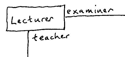
Can you think of any other roles for a Lecturer object?
In the diagram, the Order Line end of the association from Order is called line items (perhaps better written as lineItems). If there is no label, you name an end after the target class, so, for instance, the Customer end of the association from Order would be called customer.
An association end also has multiplicity, which is an indication of how many objects may participate in the given relationship. In the diagram, the * on the Order end of the association with Customer indicates that a Customer may have many Orders associated with it, whereas the 1 on the other end indicates that an Order comes from only one Customer.
In general, the multiplicity indicates lower and upper bounds for the participating objects. The * represents the range 0..infinity. A Customer need not have placed an order and there’s, in theory, no upper limit. The 1 stands for 1..1. An Order must have been placed by exactly one Customer. (Many people feel that using the symbol * is a bad idea; they think it's better to write 0..* to avoid confusion. I'm one of these people, incidentally.)
The most common multiplicities in practice, then, are 1, 0..*, and 0..1 (you can have none or one).
Key ideas in the above:
association, subtype (together examples of relationships),
association ends (or roles), roles names,
multiplicity (called cardinality in classic data modelling).
Specification Perspective and Implementation Perspective:
Within the specification perspective, associations involve responsibilities. You can't have an association unless objects take responsibility for maintaining the association, through their features, whether their attributes, their operations or both.
The diagram implies that there may be one or more methods associated with Customer that will tell me what orders a given Customer has made. Similarly, there may be methods within Order that will let me know which Customer placed a given Order and what Line Items are on an Order. Just whether any of these possibilities are in fact the case depends on the responsibilities allocated.
In Java, we could possibly infer something along these lines for the Order class:
class Order
{
public Customer getCustomer();
public Set getOrderLines();
…
}
An association also implies some responsibility for updating the relationship. There should be a way of relating the Order to the Customer. Again, the details are not shown; it could be that you specify the Customer in the constructor for the Order. Or, perhaps there is an addOrder method associated with Customer. You can make this more explicit by adding operations to the class box, as we will see later.
These responsibilities do not imply data structure, however. From a specification-level diagram, we can make no assumptions about the data structure of the classes. I cannot and should not be able to tell whether the Order class contains a field for Customer, or whether the Order class fulfils its responsibility by executing some code that asks each Customer, whether it refers to a given Order. The diagram indicates only the interface – nothing more. The matters raised in this paragraph are the responsibility of the implementation perspective.
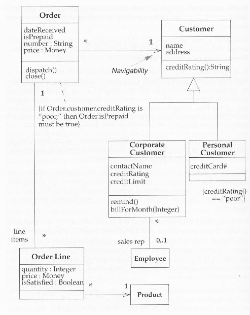
5. Navigability:
We can add a couple of arrows on the association lines. These indicate navigability. Here's the same diagram as before with possible navigabilities drawn in. The arrow on the association line from Order to Customer shows that an Order instance has the responsibility to tell what Customer instance it is for, but that a Customer instance is not obliged to tell you what Order instance it relates to.
In a specification model, this would indicate that an Order has a responsibility to tell you which Customer it’s for, but a Customer has no corresponding responsibility to tell you which Orders it has. However, repeating what I wrote above, I cannot and should not be able to tell whether the Order class contains a field for Customer, or whether the Order class fulfils its responsibility by executing some code that asks each Customer, whether it refers to a given Order. The diagram indicates only the interface – nothing more. The matters raised in this paragraph are the responsibility of the implementation perspective.
Navigability serves no useful purpose on conceptual diagrams, but they’re relevant on specification and implementation diagrams. The diagrams shown above are closer to implementation level diagrams than they are to anything else.
In short the conceptual perspective doesn't say which objects can tell you about other objects. The specification perspective does however give you this information; we now know which objects we can ask for information about other objects. However, it's not until we get to the implementation perspective that we discover exactly HOW all this is done in terms of what actual private attributes and private methods exist.
Navigabilities can be unidirectional (arrow on only one end) or bidirectional (arrows on both ends).
6. Naming Associations:
There are several ways of naming associations. Traditional data modelling likes to name an association using a verbal phrase so that the relationship can be used in a sentence. Most object modellers prefer to use nouns to name the role of one or other of the ends, since that corresponds better to responsibilities and operations.
An example of this from another context might be the class Lecturer, which can play a number of different roles such as teacher, examiner, researcher, syllabusDeveloper, libraryCommitteeMember etc.
Some people name every association. Others name an association only when it improves understanding. Don't name an association with names like “has” or “is related to”. If there’s no name on the end, then you might consider the name of the end to be the name of the attached class, as previously indicated.
7. Attributes:
Depending on the detail desired in class diagrams (see end of section 3 above), the notation for an attribute can show the attribute’s name, type, and default value. The UML syntax is
visibility name: type = defaultValue
Visibility is + (public), # (protected), or – (private)
example: + retirementAge : int = 65
So what’s the difference between an attribute and an association?
From the conceptual perspective, there’s no difference. An attribute carries just another kind of notation that you can use if it seems convenient. Attributes are usually single-valued. Usually, a diagram doesn’t indicate whether an attribute is optional or mandatory, although you can do this by putting the multiplicity after the attribute name in square brackets. For example:
dateReceived[0..1]:Date
The difference occurs at the specification and implementation levels. Attributes imply navigability from the type to the attribute only. Furthermore, it’s implied that the type contains solely its own copy of the attribute object, implying that any type used as an attribute has value rather than reference semantics.
It’s best to think of attributes as small, simple classes, such as strings, dates, money objects, and non-object values such as int and real.
8. Operations:
Operations are the processes that a class knows how to carry out.
Operations most obviously correspond to methods on a class. At the specification level, operations correspond to public methods on a type. Normally, you don’t show those operations that simply process attributes (the getters and setters) because they can usually be inferred. In the implementation model you may want to show private and protected operations as well, but only in the implementation perspective.
Nearly the full UML syntax for operations is
visibility name (parameter-list) : type-of-returned expression
Visibility is + (public), # (protected), or – (private)
An example operation on account might be:
+ balanceOn (date: Date) : Money
Within conceptual models, you shouldn’t use operations to specify the interface of a class. Instead, indicate the principal responsibilities of that class, perhaps using a couple of words summarising a responsibility in the manner of CRC cards (see elsewhere in these notes).
9. Queries and Modifiers:
It is useful to distinguish between operations that change the state of a class and those that don’t. UML defines a query as an operation that gets a value form a class without changing the system state – in other words, without side effects. You can mark such an operation with the constraint {query}. See below in these notes for information on constraints. Additionally one might refer to operations that do change state as modifiers.
It’s helpful to highlight queries. Queries can be executed in any order, but the sequence of modifiers is important.
10. Operations, Methods and Polymorphism:
Another distinction is between operation and method. An operation is something that is invoked on an object (the procedure call) whereas a method is the body of a procedure. The two are different when you have polymorphism. If you have a supertype with three subtypes each of which overrides the supertype’s banana operation, you have one operation and three methods that implement it.
UML uses the term feature to mean either an attribute or an operation.
Thus within a class
features = attributes + operations
11. Generalisation and Polymorphism again:
A typical example of generalisation involves the personal and corporate customers of a business. They have differences but also many similarities. The similarities can be placed in a general Customer class (the supertype), with Personal Customer and Corporate Customer as sub-types. The similarities are abstracted to a supertype.
This phenomenon is also subject to different interpretations at the different levels of modelling:
Conceptually:
Conceptually, we can say that Corporate Customer is a subtype of Customer if all instances of Corporate Customer are also, by definition, instances of Customer. A Corporate Customer is then a special type of Customer. The key idea is that everything we say about a Customer – associations, attributes, operations – is true also for a Corporate Customer.
Specification:
Within a specification model, generalisation means that the interface of the subtype must include all elements from the interface of the supertype. The subtype’s interface is said to conform to the supertype’s interface.
In other words, I should be able to substitute a Corporate Customer within any code that requires a Customer, and everything should work fine. The Corporate Customer may respond to certain commands differently from another Customer (using polymorphism), but the caller should not have to worry about the difference. (see this link for a discussion of the idea of polymorphism.)
Implementation:
Generalisation at the implementation perspective is associated with inheritance in programming languages. The subclass inherits all the methods and fields of the superclass and may override inherited methods.
12. Constraint Rules:
Much of what is done in drawing class diagrams is indicating constraints (see definition, in purple, of the general English word constraint at the beginning of this html page).
For example: The diagram shows that an Order can be placed only by a single Customer. The diagram also implies that each Line Item is thought of separately: You say 40 red widgets, 40 blue widgets and 40 green widgets, not 40 red, blue and green widgets. Further, the diagram says that Corporate Customers have credit limits but Personal Customers don’t.
The basic constructs of association, attribute and generalisation do much to specify important constraints, but they cannot indicate every constraint. These constraints still need to be captured and shown; the class diagram is a good place to do that.
The UML allows you to use anything to describe constraints. The only rule is that you put them inside braces. Some people like using informal English, emphasising readability. The UML also provides a formal Object Constraint Language (OCL).
13. When to Use Class Diagrams:
Class diagrams are the backbone of nearly all OO methods, so you will find yourself using them all the time.
The trouble with class diagrams is that they are so rich that they can be overwhelming to use. Here are a few tips:
· Don’t try to use all the notations available to you, that you find in thick books. Start with the simple stuff in these notes: classes, associations, attributes, generalisation, and constraints. Introduce more advanced notation such as aggregation and composition (not covered in this html document but discussed in the next link on the web site) etc. when you need them, and only if you need them.
· Fit the perspective from which you’re drawing models to the stage of the project.
¨ If you’re looking at the domain, draw conceptual models.
¨ When working with software, concentrate on specification models.
¨ Draw implementation models only when you’re illustrating a particular implementation technique.
¨ Don’t draw models for everything; instead, concentrate on the key areas. It’s better to have a few diagrams that you use and keep up to date than to have many forgotten, obsolete models.
The biggest danger with class diagrams is that you can get bogged down in implementation details far too early. To combat this, focus on the conceptual and specification perspectives. If you run into these problems, you may well find CRC cards to be extremely useful.
14. a 2-D point object - Example of alternative implementation decisions
At conceptual level, we think about having 2-D point objects on the co-ordinate plane, and matters such as any associations they might have with other objects, such as shapes. At specification stage, objects of this point type have been given the responsibility, among other responsibilities, probably, of reporting, to other objects, their co-ordinate values in either (a) x, y format (Cartesian) or (b) r, θ format (polar), something that had not yet been decided on at conceptual level. What alternative responsibilities, incidentally, could we have given these point objects?
What implementation possibilities do we have, for this one responsibility? There are three that I can think of:
implemenation possiblity 1:
Each Point object has x, y attributes and also r, θ attributes, and reports them as necessary. This allows fast reporting at the expense of extra data storage.
implemenation possiblity 2:
Each Point object stores its co-ordinates in r, θ format and, if required to report its x value does so by invoking a method in itself that calculates x = rcosθ, and if required to report its y value invokes a method in itself that calculates y = rsinθ.
implemenation possiblity 3:
Each Point object stores in
co-ordinates in x, y format and, if required to report its r value does
so by invoking a method that calculates
r = Ö(x2 + y2) (Pythagoras'
Theorem) and
if required to report its θ value invokes a method in itself that
calculates θ = tan-1(y/x).