| Ease & cost | This is a very easy and quick modification that costs almost nothing. You should do it all in one day. The engine stays in place, you just take the head off. |
| Effect | Bang-for-buck, it is one of the best modifications you can make. You get : More power at all revs · Improved fuel consumption · Cooler pistons, which improve reliability · Reduced hydrocarbon & CO emissions . And it allows cheap and frequent top-end inspections as it dispenses with the expensive head gasket. |
| Tools | 13 & 14 mm spanners · Cross-headed ('Phillips') screwdriver. · Spark plug spanner · Vernier gauge · Torque wrench · Allen keys · Fine or medium flat file |
| Materials | 100 & 600 grade wet & dry paper · Silicone sealer · Cleaning stuff, eg Fairy Power Spray · Multicore electrical solder. |
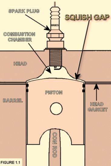
The piston goes up and down in it's hole in the barrel. As the piston goes up to the top, it traps and compresses a mix of air, oil and petrol (and some left over exhaust fumes and specks of soot). Near the top, the spark plug ignites this lot and the resulting expansion pushes the piston down with great force, providing the power.
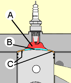
Figure 1.1, on the right, shows the piston at the top of its travels.
The piston comes close to the metal above it in the cylinder head. It would be a disaster if the piston came up further and actually hit the cylinder head. Yamaha ensures that this does not happen by leaving a generous gap of around 2mm here. This gap is the squish gap.
So the standard squish gap is around 2mm, typically 1.9mm.
The engine goes better with a squish gap less than 1.9mm. Yamaha knew this, but their production methods were not accurate enough to reliably make this gap any smaller. So they played safe and gave you a bigger gap, and less power.
However, Yamaha did manage to make some bikes more accurately, with a smaller squish gap. These are the ones they supplied for magazine tests!
It is an observed fact that an optimised squish gap makes the engine go very noticeably better, through the whole rev range. It also keeps the pistons much cooler which increases reliability.
The optimum squish gap has been found by trial-and-error over time. For the Yamaha water-cooled 350cc twins, a gap of between 0.9mm and 0.75mm is ideal. That simple finding is all that you need to know to make this modification. You can theoretically go for a slightly smaller gap on the 250cc twins, but this size of gap works well on the 250cc twins, too.
However if, like me, you like to know how these things work, here goes...
The first thing to appreciate is that the mixture does not all burn at once when it is ignited. The flame spreads surprisingly slowly from the spark, at about 100 kmh (roughly 60mph). So, if the spark where to fire right at the top, the flame would not spread fast enough to burn all the mixture before the piston descended. In order to burn all the mixture near the top, so that it can be used to drive the piston down, it has to be ignited before the piston gets to the top. During the first part of the burn then, while the piston is still rising, the combustion actually tries to push the piston back the 'wrong way' and robs power. However, when the piston reaches the top and starts to go down, there is more driving force to be had from the more completely burned mixture, and this increases power. The optimum ignition timing is a balancing act between these two conflicting results and is found by trial-and-error.
At higher revs, there is less time for the mixture to burn, so the spark has to fire even earlier. Therefore, like most engines, the YPVS ignition system automatically advances the spark timing as the revs increase.
Now what has all this to do with the squish gap? Well, bear with it for a little longer and it becomes clear.
Isn't it a shame that the energy from the early part of combustion is used to try and drive the engine backwards? Think of all that petrol being burned to decrease the power instead of to increase it. If you can reduce this part of the engine cycle, you will clearly get more power...
In the YPVS engine, the combustion chamber is narrower than the piston. This means that the mixture in the combustion chamber is nearer to the spark, and the flame spreads through it quicker. This reduces the ignition advance required to get complete combustion, which reduces the power-robbing part of the engine cycle just like we wanted. However, the narrow combustion chamber leaves an inconvenient cranny round the edge called the squish gap, which we saw earlier.
The mixture in the squish gap will not burn at all in the initial combustion. Not only is it too far from the spark, but the flame will not travel along the squish gap because the metal of the piston and cylinder head is cool enough to extinguish the flame. When the piston descends and the squish gap widens, most of the mixture in it will still not burn because the piston is racing away from the burning mixture much faster than the flame can travel. Furthermore, it is too late in the combustion cycle for any combustion of this mixture to add much of its power to the cycle.
With a stock squish gap of 1.9mm, about 18% of the mixture is in the squish gap rather than the combustion chamber, so 18% of the mixture is removed from the initial combustion process.
We can get much of that 18% of the mixture back working for us by making the squish gap as narrow as possible. "As narrow as possible" does not mean zero ! There are two things which limit how far we can go. First, the gap gets narrower when the engine revs higher because the con-rods stretch a little and there is a bit of play in the bearings. So, if we set the gap to zero in a stationary engine, the piston would hit the head when we revved it. Secondly, if the gap is too narrow, the mixture cannot squish out into the combustion chamber quickly enough when the gap closes. This creates very high pressure, which causes harmful detonation - the explosion of the mixture at once. So, the optimum gap is a balancing act between these things. It is found by trial-and-error to be 0.75 to 0.9mm for the 350cc twins. At 0.9mm, around 11% of the mixture is in the squish gap. That's returned 7% of the mixture to the combustion process compared to the stock 1.9mm gap.
Having said all this, that is not the whole story. Reducing the squish gap below the magic 1mm mark seems to perk up the engine disproportionately, for reasons which are not well understood. It also makes the engine less susceptible to detonation than increasing the compression ratio by other means. That just illustrates how little we really know about what happens inside the engine...
So how does this cool the piston ? When the cool, unburnt, mixture is squeezed out of the squish gap by the rising piston, it plays over the piston surface and cools it. Not only does this improve reliability, but reducing the heat flowing through the piston also increases power: Heat flow through the piston increases the pressure of the incoming mixture under the piston, which reduces the amount of mixture that is drawn in.
Reducing the squish gap also reduces the compressed volume, which increases compression. This actually optimises the compression ratio for the stock YPVS because Yamaha have left a good bit of slack here, too. There are two types of cylinder head on the YPVS models, marked Y1 and Y2. They are clearly marked on the top. The Y2 is the higher-compression head. With a squish gap of 1.9 mm even the 'high compression' Y2 head gives a lowly compression ratio of 6.0:1 (measured from the top of the exhaust port). With a squish gap of 0.9mm the compression ratio rises to 7.1:1, which is actually a pretty good ratio for road use with ordinary petrol. As a rule of thumb, you can push the compression ratio to perhaps 7.7:1 on this engine with ordinary petrol, and retarded ignition, before detonation happens. However, 7.7:1 is not a hard and fast rule, and 7.5:1 is probably a better safe maximum.
The increase in compression can get a bit hairy when the engine has been overbored, which increases the compression ratio. For instance, with a 1 mm overbore and taking the squish gap right down to 0.75 mm, the compression ratio will rise to 7.5:1, which some would consider to be right on the limit for use with normal petrol. If you fall into this area, you might want to consider raising the exhaust port to 26mm from the stock 27.5 mm purely to lower the compression, rather than for other performance considerations. That would lower the compression from 7.5:1 to 7.2:1 in the above examnple, back into the safe area.
You will measure the squish gap to find out how much it needs to be reduced. Then you will remove the head and dispose of the head gasket, which will reduce the squish gap by around 0.7mm. Even without the head gasket, the gap is probably still too big, so you will sand down the head another 0.3mm or so until the gap is around 0.9mm. Finally, to make sure that the head seals without a gasket, you will 'lap' the head to the barrels by rubbing them together between fine wet-and-dry sandpaper so that they fit together snugly.
I advise you to aim for 0.9mm rather than for 0.75mm because the lower value will leave you no room for error. It may also give too-high a compression ratio if you have a large overbore. In my experience, you will end up with a gap smaller than the one you aim for rather than larger.
It is especially important to be really clean for this work. Any trace of grit can destroy the finish between the head and the barrels.
If you are working outside. First, you know you shouldn't really work outside, but most of us do it. Just make sure that you have a clean surface nearby for your tools, and put a clean mat on the ground in case you drop anything (and to save your knees when you kneel down).
Clean up the outside of the bike, particularly round the top of the engine, where you will be working. Clean up all the tools you will use. There are only a few to clean. Then clean your hands. Now, nothing will get dirty.
Have clean containers to keep the bits you'll take off.
Sorry to nag you if you already work clean. I've seen too many people who put every bolt they take off straight on to the ground…
You want to know how much to reduce the gap, and that depends on the size of the gap to start with. The gap is different on every bike, so you have to measure your own gap. It will probably be around 1.9mm but it could be 2mm or 1.8mm for example. If it's below 1mm, someone else got there before you !
You measure the gap by taking out both spark plugs and poking some solder into the squish gap, through the spark plug hole and right to the cylinder wall. Turn the engine gently with the kick-start: The piston will squash the solder to the width of the squish gap. You then take out the solder and measure how wide it is with a vernier gauge.
Tip: you can buy a plastic vernier gauge for less than a quid, and they read to 0.05mm which is all we need here.
If the solder is thinner than the gap to start with, it won't be squashed at all and you will be none the wiser. In this case, twist two or more strands of solder together to make it thicker.
Push the solder to the side of the piston, rather than to the front or back. This is because the piston can rock back-and-forth slightly on the pin that holds it, which will give a false high reading at the front & back. However, the piston cannot rock much sideways. Ideally, use two pieces of solder – one at each side – to neutralise any rock.
Measure both cylinders: they could be different. If they are dramatically different, ie by much more than 0.1 mm or so, you have to correct this before proceeding. Seek advice if you cannot find and cure the problem yourself. Maybe one side of the head is tightened more than the other, of there is some dirt on the gasket. Or it could be something more sinister like a bent con-rod, or a badly worn bearing.
Remove the head as per a service manual. You'll need to drain the coolant at both barrels, and remove the two coolant hoses attached to the head. Then release the ten nuts that hold the head, progressively and in reverse order, 10 down to 1. Each bolt is numbered on the head.
Pull the head away, then pull off the gasket and clean up any debris.
Remove the stub for the coolant pipes from the bottom of the head. It has two hexagon bolts.
Clean the head, including the inside of the combustion chambers, thoroughly. Fairy Power Spray or similar will give you a surgically clean head in short order.
Tip: now is a good time to remove any carbon from the top of the pistons, and to inspect the inside of the bores for wear. Scrape off the carbon with wire wool or a soft scraper and vacuum up the debris as you go. You can also check the exhaust port height now. If it is stock, it should be 27.5 mm below the edge of the piston when it is at its very topmost.
Plug the barrels with foam, or clean cloth, to stop dirt getting in.
Make sure that the top of the barrels and the head are clean, then bolt the head back on temporarily. Measure the squish gap as before. It will be smaller without the gasket. The amount to remove is the new squish gap minus the gap you want. If you aim for 0.9mm and the new gap is 1.2mm the amount to remove is:
1.2mm - 0.9mm = 0.3mm
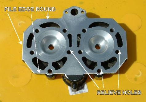
File an angle a couple of millimeters all round the outside of the head. The photo opposite shows a head after this has been done. It is very hard to see at first in the picture, but you can just make out the shiny angle that has been filed all round the outside. This prevents a razor sharp right-angled edge from building up as you lap the head. A razor sharp edge would be a nuisance that catches on the wet-and-dry paper when you rub the head over it. Imagine trying to iron a shirt with an iron that had a razor-sharp edge.
*IMPORTANT* Relieve the outside of the bolt holes in the bottom of the head. This means, widen the holes slightly at the bottom. You can see this in figure 1.2, opposite, if you study it carefully. You are looking at the thin angle cut away round each hole. You should widen the bottom of each hole by a millimeter or so. Use a hand drill and a conical grinding stone or other suitable implement.
Relieving the holes makes it much easier to seal the head to the barrels: When you tighten the head bolts, they pull very hard on the studs, which causes the face of the barrels at the base of the studs to well up slightly. Normally, the head gasket takes up this distortion. However, we are not using a gasket, so this distortion could makes it difficult to seat the head snugly on the barrels. Relieving the holes allows the metal to well-up into the base of the holes when you tighten the studs, without lifting the head way from the barrels.
Incidentally, figure 1.2 very nicely shows the squish band, which we re making all this fuss about.
Tape a sheet of coarse wet-and-dry sandpaper to a piece of ordinary 'float' glass, as used for house windows. Place the glass on a flat, solid, surface.
Rub the head back and forth over the sandpaper until the required amount has been removed. Keep the head flat on the sandpaper.
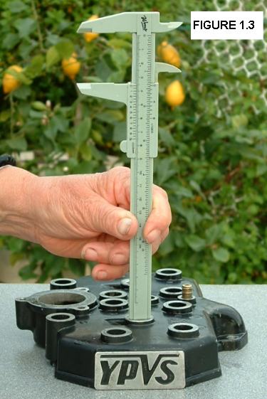
Periodically measure how much has been removed by probing with a vernier gauge through the spark plug hole, as shown in the photo opposite. Measure through both spark plug holes to check that the head is being sanded evenly.
This is a long and tedious procedure. Allow two hours of sanding.
Most people take the head to an engineering shop instead and pay to have it machined down. Even if you live near a machinist who will drop what they are doing to machine your head, the round trip is likely to take a lot longer than the two hours it would take doing it yourself. And it is more expensive!
Before you can smooth the top of the barrels, you need to remove the ten studs that stick out of them. To remove each stud, put two nuts on it, and tighten them against each other so that they lock together. Now turn the bottom nut to remove the stud. You will need an open-ended spanner, not a socket, because a socket can only turn the top nut. They don't put up much of a fight.
Clean the top face of the barrels and the studs.
Ensure that the bores are plugged with cloth that doesn't stick out beyond the top.
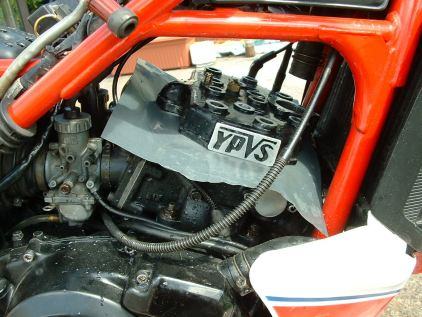
Place a piece of wet-and-dry paper on top of the barrels, and place the head on that, as shown in the photo opposite.
You are mainly interested in the three-millimeters or so round the bores. This area should be completely smooth and shiny on the head and on the barrels. Minor imperfections are OK elsewhere because they will seal with silicone. For instance, in figure 1.2, there are still some marks near the top right bolt hole of the left-hand bore. They are OK here, but they would not be OK near to the bore.
Remove the cloth used to plug the bores, and wipe any residual dampness from the bores.
There will be water in the stud holes: suck it out with a small tube. Replace the studs.
Smear a VERY THIN layer of silicone on the joining surface of the head. It should be so thin that, even if it's coloured, you can still see through it. If 'snots' of silicone squish out when you tighten the nuts, you have used far too much. Remember that the same snots will also appear inside the bores.
Put back all the bits you took off and refill the coolant system. Now might be a good time to change the coolant mixture if that has not been done recently.
Tip: Notice how the head 'slops' back-and-forth and side-to-side before you tighten the head bolts. The engine goes best when the head is centered, so pay special attention when tightening the nuts, so that the head stays centered. If you have the bike on the side-stand, for instance, the head is likely to be off to one side unless you pay attention to supporting it when you start to gently tighten the first bolt or two.
Start her up! Straight away, you will notice that the bike idles faster, and responds to the throttle much quicker. Unfortunately, it will also idle richer (the revs take longer to drop when you blip the throttle slightly). Do a short the warm-up ride using only moderate power: notice that the bike is more eager all round.
After the warm-up ride, reduce the idle speed to spec. Adjust the idle mixture so that it responds quickest to a small throttle blip, and also so that the revs drops quickest after the blip.
Now leave the bike overnight for the silicone to set. Next day go for a longer, harder, proving ride. You might need to lower the jet needle or change to a smaller main jet.
Tip: If you do this modification at the same time as Improving The Air Filter, the net effect on the mixture will be much less: Improving The Air Filter makes the mixture leaner while this one makes it richer. The two together partly cancel out the change to the mixture. So, you will need to make less adjustment to the mixture.
Theoretically, this modification will require the ignition timing to be retarded a little. However, the stock ignition is already somewhat retarded compared to optimum, so the stock timing might well be OK. However, you may want to experiment with retarding the ignition a little by trial-and error, to get the very most out of this modification.
The ignition timing is not adjustable on the stock bike, so there is a page in this tuning guide which tells you how to modify the bike so that you can adjust the timing. It is safe to retard the ignition timing because it generally makes the engine run cooler and you just loose power if you over-do it. However, advancing the ignition beyond optimum can dramatically increase the engine temperature and melt the pistons.
Chatting down the pub, everyone seemed surprised at the figures I gave above; how much mixture is in the squish gap, and how much the compression ratio changes when the squish gap is reduced. The surprise bordered on disbelief, as if the figures stemmed more from the excellent Guinness I was drinking rather than anything scientific I had done before going to the pub. They all seemed to expect the figures to get bigger with every pint.
If you are interested in this sort of thing, click here to see how I got the figures.