
Gerard Feeney paves the way to successful 'Instant Aeromodelling Gratification"!
Love 'em or loathe 'em, you can't ignore 'em! ARTF model aircraft designs are becoming hideously popular on an international level due, one supposes, to their much-hyped attributes of fab finish, effortless assembly and superb 'up and at it' performances after a couple of minutes' work. This concept actually works well for many modellers; but for others, due to a fatal real-life mix of dubious kit quality and half-hearted modeller commitment, the end-product turns out rather disappointing! If you want to see a prime example of what can go wrong with ARTF assembly, have a look at the April 1998 issue of 'Radio Modeller' magazine.
'Instant' R/C aircraft demand their own particular brand of 'assembler TLC' to maximise user-satisfaction in the flying/operational longevity departments. Taking a little extra time to sort out potentially fragile/inaccurate airframe details can make a great deal of difference; the model's life-span will be actually increased (assuming you don't crash it!) due to attention to detail - and that can only promote added ownership satisfaction…
Instant Attraction?
Okay, so it's a gorgeous looking box - but what about the individual component quality of those ready-made aeroplane-shaped bits inside? Assuming it's a (for want of a better word) 'traditional' built-up wooden structure, covered by some sort of foam skin/printed self-adhesive overlay, the important areas to note are those of constructional accuracy and the internal/external 'bonds' and finishes.
The major airframe items may be poly-bagged; if so, remove the wrapping to inspect the structural 'trueness' of each part. Are the wings and tail/fin, plus the control surfaces themselves, straight and warp-free? Is that 'factory-built' fuselage in fact totally symmetrical in the top/bottom plan-views, and from the nose/tail end-on views? Are the tailplane slots lined-up properly? Is the fin slot straight relative to the fuselage plan-view centreline? Mildly warped flying and control surfaces can be reworked reasonably successfully (see later), but a banana-shaped fuselage is the kiss of death as far as flying accuracy is concerned. If this irreversible building error is evident, it would be wise to choose another kit! Think such structural cock-ups can't happen? Wrong! I saw a very twisted pre-built fuselage in a well-known ARTF brand kit recently; needless to say, I didn't buy the kit!
The glue joints of traditionally-constructed ARTFs are another source of pre-purchase concern! Are there 'orrible glue blobs all over the place and/or are some joints sloppy fitting with large gaps present? I've seen some examples with only the covering material holding things together! I'm afraid that excess adhesive application is hard to manage, but it's possible to carve excess epoxy off accessible joints with a new sharp stout scalpel blade. Gappy joints which are accessible are easily treated by simply running in some thick cyano or Deluxe Materials' 'Super Phatic' as appropriate. However, any dodgy inaccessible joints have to just remain untreated…
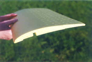
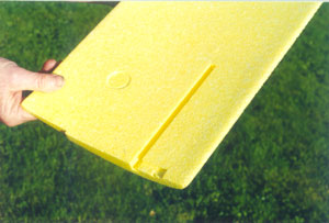
If your proposed ARTF craft features a moulded foam, ABS or GRP fuselage, and bare foam or pre-covered veneer/balsa-skinned foam flying surfaces, there may well be less to worry about! Keep an eye out for dodgy fuselage joint-lines where half-shells meet, or where foam components come factory-fused. Notice too the amount of excess flash present on moulded parts. Is it easily trimmed away? Will it interfere with part fits? Floppy half-shell seams can be internally reinforced with very thin glass cloth and Deluxe Materials' 'Super Crylic' or slow epoxy. Foam wings which are of the aforementioned pre-moulded/pre-skinned/pre-covered variety are normally quite accurate in my experience. If they aren't, don't buy the kit - there is nothing you can do (that I'm aware of) to easily straighten 'em out again permanently! Do check also, even if the panels are ultra-accurate, for patches of lifting film and/or foam skin underlay on pre-decorated wings. More on that topic later.
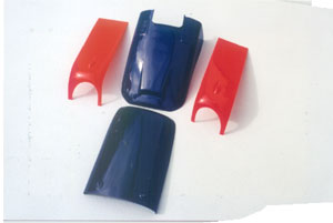
Of course, plastic moulded bits like cowls, wing and tailplane tips, tailplane fin base fairings, fuselage belly pans, and wheel spats, can be common to either type of ARTF airframe. When such items come factory-fitted, check their security, surface finish and apparent durability. Gappy or loose edge fits can be made good with cyano, epoxy or Super Crylic, if the misalignment is minor. If workmanship is really poor, consider your choice of kit! Where such mouldings have to be fitted by you, do try to check just how well they will engage the main airframe structure. Even with the host moulding sheet still attached, things like open-ended cowl halves and wing tips can usually be manoeuvred into position. Observing how, for example, the split cowling halves relate to the fuselage top-view centreline, and how well they hug the front firewall cross-section, quickly gives an idea as to whether the component is over- or under-size.
The actual exterior finish of ARTF aircraft, so often one of the major hype-up points of the 'hard-sell' routine, can be a tad uninspiring - get an eyeful of that unsanded wooden model structure! Frequently I've recoiled at wrinkled and/or unstuck covering film, covering film applied indiscriminately over gluing areas, and roughly coated paint and fuel proofer! These failings are generally fairly easy to treat, as we shall discuss in due course. For some reason, the surface finishes of the moulded airframes I've sampled seemed consistently better, so I just left 'em as they came! The decorative decals still had to be stuck on though…
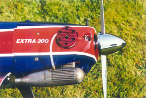
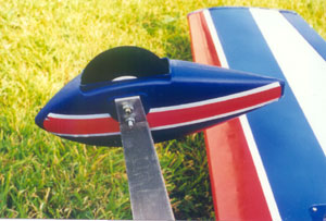
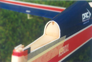
ARTF kits love to give you self-adhesive decals to cover up joint-lines, and of course to make your aircraft look just like the other half-million in existence! The Hobbico 'Extra 300' pictured here uses self-adhesive strips to hide the unconventional horizontal joint-lines between its plastic cowl shells. A good idea, but that trim tape needs to be most flexible to go around the curves! These sticky-back decals and tapes are mostly of good quality and, providing you cut the design closely with a Number 11 scalpel blade and/or sharp scissors, they can look neat. Lifting self-adhesive trim design edges can cause problems on compound-curve surfaces like wheel spats. I run some thin cyano under the lifting edge and then press down with the scalpel tip for a minute or so. That remedy usually helps so long as the part is grease-free. Nicking the decal/tape edges is also helpful. One or two coats of clear polyurethane varnish adds extra edge protection also.
ARTF accessory packs are, in my experience, very comprehensive and normally of good quality. I've rarely had to bin any items - except for the occasional weak clevis, or those terrible 'soft alloy' cross-head screws! Again, if you feel that any of the supplied accessories are suspect, replace 'em with proper model shop-bought substitutes.
Instant aeroplane assembly manuals tell you how to 'stick it' in varying degrees of detail! Some are little more than a series of badly drawn sketches with brief typo'd captions. Others are impressive photo-illustrated missives, which really reach the nitty-gritty assembly nuances - assuming you take the time to study all the info presented! As with 'normal' built-up R/C model kits, do study the manual a few times before 'letting fly' with the glue! Sure, it looks like an ultra-simple piece of assembly work - but there may be hidden constructional pitfalls waiting to really trip you up! A few dry-runs, in advance of the actual sticking, are a very good idea also - just to confirm that everything actually slots together as designed.
Build me, Shape me!
ARTF airframe assembly can be 'broken-up' into the following areas: wing half joining; wing/fuselage attachment; tailplane/fuselage attachment; control surface hinging (if not pre-done); fuselage/flying surface alignment; fuselage fitting out (this comprises as applicable); engine/tank/cowl installation; undercarriage fixing; radio gear installation and cockpit/canopy attachment. Let's go through these areas, more or less in the order listed.
Brace Yourself!
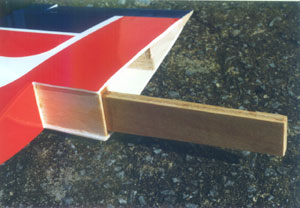
Ply dihedral braces, feeding into pre-formed wing root slots, join most ARTF wing panels together. Whether these braces are laminated 'sandwiches' or one-piece affairs, sand them well with 180-grit glass-paper to 'key' them thoroughly before plugging 'em in. if using epoxy (slow variety!) for this job, ensure that clamping pressure doesn't cause the separate brace pieces to slide out of alignment. Guess how I found that problem out?!
Epoxying the brace(s) into one wing half root slot with 30-minute epoxy, and allowing it/them to set really hard overnight before joining both wing halves, is my favourite way of doing things. With the brace(s) thus properly anchored in one wing panel, it's much easier to feed on and align the remaining wing half. Tightly tape the wing halves together when the roots are lined-up, then wipe away excess epoxy with the 'Mk. One Fingertip' and scrap balsa scrapers.
The wing root slot/brace thickness fit is another area which can cause some Valium-consumption increases! Under-size wing root slots are indeed rare, but not unknown! If this is the case, razor plane or sand the top/bottom, front/rear brace surfaces until the push-fit is snug. A final sanding should ensure a smooth mating of parts. Don't leave clearances too tight or glue will be forced out again!
Slightly over-size wing root slots aren't too much of a problem. Just fill the slot interiors with generous amounts of 'poured in' slow-setting epoxy before brace insertion takes place. That epoxy is a good gap filler! Now, push in and remove the brace(s) several times to coat the mating surfaces fully. Looking at the 'evenness' of the brace adhesive coating is a good indicator of the relative fits. Coat the braces again lightly with epoxy before finally pushing it/them fully home. Again, you'll need a scrap balsa scraper to remove excess oozing adhesive. Internal 'epoxy hydraulic pressure' may now cause the brace(s) to slide outwards once more! If this happens, tape it/them in place lightly until the glue goes off.
The 'structural integrity' of built-up wings will become evident now! I've had epoxy burst through into the wing interior due to gappy root structure joints - yuck! If this happens, rotate the wing panel in the 'looping' plane; this action helps to control the adhesive overflow pattern.
Bare foam or pre-skinned/covered foam wings are joined in a similar way. If the joiner slots extend to the wing top/bottom outside surfaces, balsa and/or film strips may be used to cover the channels. Use adhesive sparingly when installing such braces! Be careful when clamping/taping bare foam wings together, to avoid dents occurring.
Centre of Attraction?
Moulded plastic sheet fairings cover many joined ARTF wing centre sections. These items are usually meant to be epoxied in place - often, on top of unsanded covering film! Personally, I like to impact-glue these fairings in place above and below the wing middle, having first given the covering (if present) a jolly good sanding. You'll have to use epoxy if bare foam wings need the centre section treatment, as contact glue will eat them!
The chord-wise dimension of centre section plastic fairing skins is very often over-long. It is an easy matter to carve off excess plastic with a Number 11 blade, with the lower surface plastic skin fitted first. After the lower one is beautifully trimmed along its trailing edge, the top skin is stuck on and trimmed as necessary.
On some models, a strip of self-adhesive vinyl goes on top of the wing centre joint-line. This is a reasonable method of hiding the break, but I've had to apply lightweight filler to even up wing root contours before sticking the tape in position, on quite a few ARTFs. The effort is worth it though!
A ply wing bolt plate may also be fitted on the wing centre section trailing edge. Again, I use contact glue to fasten this item. I pre-cover such plates before mounting them if at all possible - assuming they're not factory-finished. These plates are an excellent preventative measure against trailing edge bolt or band 'bite'. Fit 'em on all your flying models!
Holdin' On!
In common with other flying models, ARTFs keep their wings on with dowels and bolts or rubber bands. With leading edge dowels, engaging in the fuselage former, and a captive bolt trailing edge hold-down, you'll have a streamlined looking airframe 'ready to roll'. The trusty rubber bands, tensioned across the wing middle, from leading edge/trailing edge fuselage dowels, will allow essential 'give' on trainers.
With either form of wing attachment, you'll probably get pre-marked or fully pre-drilled holes to stick the bolts and dowels into. If marked out by the builder, measure the dowel/bolt hole centres carefully. Leave the wing bolt holes just 1/16" diameter initially if marking out by hand. Even pre-drilled holes may need some filing to get the wing/fuselage alignment 'just so'. With bolted-on wings, after establishing the leading edge dowel/former fit, I push the wing trailing edge down onto plugged-in cocktail sticks or reversed paint-ended bolts (depending on bolt plate preparation), to mark the wing centre drilling locations. With banded-on wings, check that the dowel/fuselage 'pass-through' points are strong enough to take the band strain. Add internal 1/8" ply doublers if the fuselage structure is weak.
Tail Story.
Before gluing, dry-fit the horizontal/vertical tail surfaces into their slots, or on top of the tail-seat platform, to see how fits and alignments work out. If they're slightly crooked, trim the offending fuselage slot edge, or elevated tail-seat mount, with the trusty Number 11 blade and/or some 180-grit glass-paper stuck to a piece of 1/8" ply. If the fuselage slots need major relieving to align the tail parts, some scrap balsa slivers, cyanoed to the adjusted slot edge, will re-establish a true tight tailplane fit prior to first gluing the horizontal stab in place. The fin is then coaxed into position. I prefer PVA or slow-set epoxy to stick the tail surfaces - one must remember the crucial importance of adequate 'juggling time' at this critical juncture!
Foam and ABS/GRP fuselage tailplane slots can be adjusted with a Junior hacksaw, razor saw, strong scalpel, or Dremel tool, after first marking the cutting lines in pencil or masking tape. Edge smoothing is again the province of the thin ply sanding block. You need a slim sanding block to access/abrade the narrow tailplane slot edges properly. A round file is useful to shape the slot leading edges.
Internal scrap balsa platforms or seating strips cut from 1/4" sq. balsa can be installed in the rear-ends of thin-gauge moulded fuselage shells to increase the gluing/alignment area prior to tailplane insertion. I make the platform by just placing some stiff card across through the tailplane slots. I mark the exterior rear fuselage taper each side on the card, then transfer its shape to the wood. I cut out the wood 'wedge' minus the fuselage shell wall thickness dimension, and it's then ready to fit after a spot of edge-sanding. The platform is teased in through the tailplane slots, or down from the radio bay. In the latter case, I cyano the wedge to a balsa strip and gently feed it up to just under/over the model's rear-end tailplane slots.
Tail seating strips are skewered on a Number 11 blade and fed through the tailplane slots - if wide enough. Cyano, dribbled in through the tailplane slots again, will hold either the tail platform or the tail seating strips very firmly.
All too often, ARTF model aeroplane fins just butt down onto the horizontal tail, without actually slotting in place. A plastic fairing shroud then envelopes the fin base/horizontal tail junction, simultaneously continuing the rear fuselage top deck lines in the process. This system works quite well - assuming all the part joints are really snug.
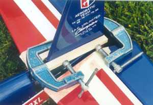
I like to reinforce the fin base/horizontal tail joint, whether the fin is butted or slotted in place, with scrap balsa fillets epoxied on after the fin is aligned and its glue joints have set hard, but before the plastic fairing shroud goes on. Ensure that the balsa fin base fillets are relieved to allow the plastic cover to seat properly! Sand the plastic fairing shroud interior and the horizontal tail/fin base gluing areas thoroughly before starting work on the tailplane mounting job at all. I personally favour slow epoxy and small clamps to stick and hold the fin base shroud firm as things cure nicely.
On The Level?
I align ARTFs (and all flying models) by first bolting/banding the wings to the fuselage. Having established a reasonably level-looking wing front-view (one wing seat may need sanding), I measure from the wing tip trailing edges to the fuselage sternpost outer edges. I tweak the wings in plan-view until this dimension matches each side, within about a 1/16" margin of error. Once this is achieved, I mark the fuselage side lines above or below the wing centre section, depending on the airframe configuration, having at this time fully tightened up the wing grip. Next, I fit the horizontal tail, relying on the slot friction and/or a single stout modelling pin to hold it steady. I then swivel the horizontal tail in top plan-view until the elevator hinge line is equidistant - give or take 1/16" - from each wing tip trailing edge. I may also use the aileron hinge line (if present) as a further alignment aid. When the tail looks straight in plan-view, I mark the fuselage taper on its top and bottom centre section. I now remove the tail to glue it finally in place, as the foregoing exercise was just to get it accurately centred first. The fin is then finally added, and I just eyeball its alignment relative to everything else! No wonder 'Feeney Fliers' flit so fabulously!
Needless to say, tailplane mounting takes place after the fuselage slots have been tweaked - if needed - and not before!
The whole airframe alignment exercise is a touch hit-and-miss, and I regularly engage in literally hours of belly-crawling and chair-climbing to reassure myself that the airframe is actually 'on the level'! I use a steel retractable tape measure and non-flexible string to gauge the relative distances but, once that glue has dried, I tear my hair out once more having spotted yet another overlooked inaccuracy! I bet the 'experts' don't have this problem?
Body Talk.
ARTF model aircraft fuselages seem to need the most fitting-out work - or, so I find! I guess we should start at the front end and work backwards from there…
Power Play.
Check the supplied engine mount arm 'beam width' is compatible with your engine. If slightly narrow, a hard plastic mount can be trimmed carefully with a Stanley knife until the engine drops in smoothly. If a supplied metal engine mount is too narrow for the engine you intend using, you may have to replace the mount - or reach for the grindstone! Over-wide mounts of either material may have to be replaced also, as it ain't sensible to fill the beam gap with a butch engine way beyond the model's recommended maximum power range. This practice is okay for seasoned fliers used to hot ships, but it's a recipe for aeromodelling Armageddon for beginners with trainers! Moulded or cast metal mounts, featuring angled lower-surface arms, will need four 'flats' cut or filed underneath to prevent 'nut strain' (?) if bolts are used to fasten the engine to the mount. With moulded mounts, self-tapping screws are absolutely fine for grasping all engine sizes from .10- 1.08 cu. ins. to the mount arms. I speak from experience here.
In some kits, the engine is bolted to a pair of alloy plates - which themselves bolt to the actual (metal) mount arms. The engine-receiving alloy plates usually need to be drilled by you; the plate/mount arm holes thankfully come pre-drilled and pre-tapped. This engine attachment system works well, and it permits powerplant removal by just undoing the larger more accessible plate bolts. Useful!
I'm wary of the oft-seen 'metal clamping plate over recessed engine lugs' engine mounting system. Here, the engine slots into recessed mount arms, then alloy plates are bolted to the mount arms over the engine lugs, thereby trapping/clamping the actual engine. If done properly, the arrangement can be satisfactory, but personally I'd not be happy restraining large-capacity engines in this manner.
Check the suitability of the mount/firewall securing bolts supplied. Are they of the 'captive' variety? Are they sufficiently long enough to permit firm mount/firewall anchorage? Are they of decent quality hard metal that won't turn to jelly when screwdriver force is applied? If the answer to any of these questions is 'no', use model shop-bought replacements. Over-long mount/firewall bolts are not a problem, and are to be preferred every time. These can be shortened easily out of the model by cutting them to the desired length using a Junior hacksaw with the bolt secured in a vice-grip or bench-vice. Screw the spiked nut on before holding the end 'waste' portion of the bolt tightly in the clamping device. Once the bolt is cut to its shorter length, the captive nut is unscrewed, thereby de-burring the ragged bolt end in the process!
I've never had any problems on the rare occasions that self-tapping screws were used to maintain mount/firewall anchorage on ARTFs or other models. I tend to avoid their use for this purpose, however, simply because the pointy ends could puncture the fuel tank! And, they're difficult to clamp and cut without slipping.
A Plate Full...
Wooden, metal, or 'laminate' engine mounting plates, which bolt or screw to hardwood beams, are straightforward things to tackle - so long as the plate/nose bearer holes align as intended! If not, the plate holes will need elongating with a small-diameter round file. It is also permissible to drill new holes about 1/2" adjacent to the misaligned ones, as bearer area is usually generous enough to allow this. Fill redundant pre-drilled holes with cyanoed scrap balsa or car body filler, depending on the mounting plate material used. The pre-cut engine opening may also require minimal edge-trimming for a snug engine fit. A Stanley knife or Number 7 wood carving blade does the business on timber plates; Paxolin or metal plates will need a flat file, razor or hacksaw to modify the edges. If your candidate engine is physically 'obese' for the plate cut-out, you may have to manufacture a new plate - bearing in mind my earlier comments regarding overly-powerful engines. Of course, if a 'blank' mounting plate is furnished, you'll be able to customise it with near surgical accuracy to suit any engine size - within reason!
Shock Treatment!
I'm amazed at the apparently crude methods used to hold electric motors onto many ARTFs! Just some rubber bands, or cable tie-wraps, may be all that straps the motor to the fuselage ply cradle or wood/plastic base-plate - but the technique seems to work fine! Do ensure that the motor anchorage pieces, regardless of material, are well and truly stuck to the airframe! If the motor ain't pre-installed, roughened surfaces and slow epoxy is the way to go. Have a glance at wooden interlocking cradle assemblies; reinforce those joints if needed with Super Phatic. With some models, I use small curtain hooks, and strong miniature rubber bands, to hold the motor tightly, having first stabilised the motor casing on its plate with double-sided tape. Just passing tie-wraps around the cradle, or through a profile fuselage nose section, is another crude-looking but effective motor 'bondage' technique!
The motor can also simply slot into a pre-cut recess in a foam airframe. On the small simple lightweight models, only a dab of epoxy may secure the (sanded) motor case! More elaborate mounts introduce ply plates for direct motor case fastening. The electric motor may also mount on inset hardwood rails, via screws or bolts going through external motor casing lugs.
'Tanks' for the Info!!
There ain't a lot I can say about ARTF model fuel tank installations - the former holes are always pre-cut to accommodate the supplied fuel tank shape precisely. (Usually!) Check that the tank fit isn't excessively tight, or it could cause operational fuel foaming. If so, try to sand the former cut-out edges with 80-grit glass-paper stuck to a 1/4" ply block. Perma-Grit sanding tools are also ideal for this task. Check also that the firewall tank neck hole will permit both adequate tank neck clearance, and un-tilted side-view tank centreline alignment. If the firewall hole is off-line, you'll need to 'get rough' again! Coarse glass-paper wrapped around a suitable diameter length of hardwood dowel, a Dremel tool router attachment, or a circular Perma-Grit rod, are all ideal for getting a 'hole' lotta satisfaction!
In theory, all plumbing runs should be just dandy as all fits are pre-aligned! Do keep an eye out for kinky feed/pressure/filler lines, and remedy accordingly. Kinky plumbing results from thin-gauge silicone tubing, coupled with over-long tube runs in confined spaces. Replace and/or cut the silicone tubing to create smooth flowing plumbing lines, at the same time being careful not to place any 'pulling' strain on the tank neck brass pipes or the engine nipples. Ensure also that the plumbing doesn't rub on the engine mount edges, and/or any 'in-cowl' hardware. Peek through the cowl's front air intake(s) or cylinder head/silencer openings, with everything that should be installed in place, to confirm that the fuel tube runs are unrestricted and unstrained. Don't forget to fit a new fuel filter also - and check it regularly!
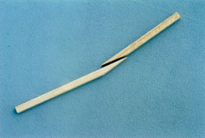
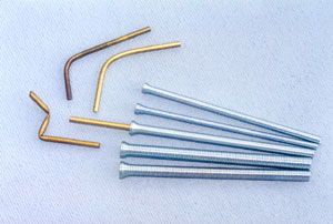
Going back a few stages, some ARTF fuel tank 'brass' pipes (which don't seem to be brass at all!) need to be bent up by the modeller, prior to tank assembly. I always got badly kinked pipes trying to bend the annoyingly soft alloy material by hand, and I frequently replaced 'em altogether with tougher pre-bent pipes from other tanks. Not any more! Now, I bend all those soft straight alloy pipes with the appropriate-size K&S 'bending spring'. These items come in a set of five tightly-wound 'coil-springs' and they are extremely useful things to have 'to hand' if you're gonna get kinky!
Basically, you just insert the straight piece of pipe into the hollow core of the matching-size inside-diameter spring, then bend it by hand from each end. I apply thumb-pressure from both hands, centred on the pipe bending area, whilst simultaneously gripping and gently bending from each end with the remainder of my available fingers. I also use the bench top, or a bit of stout scrap ply, as a 'leverage platform' to rest the 'exposed pipe end on as I bend the 'enclosed' pipe portion using thumb- and finger-pressure, with the work-piece held almost vertically upwards. Brass/alloy tube/pipe release from the bending spring can be tricky due to the 'snug' fit! It helps to bend shallower than required, then gently complete the job by hand after releasing the tube.
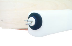
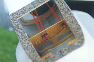
A refinement added to the Hobbico Extra 300 ARTF aircraft's fuel tank was a rigid foam 'neck brace collar'. This circular sleeve slips around the tank neck, and it guards against accidental misalignment/abrasion as one pushes the tank through the firewall opening. A great idea for all other flying models - not just ARTFs!
Glow of Contentment?
Before leaving the ARTF model i/c engine department, one must mention those darn cowl mounting blocks, and the all-important fuel proofing considerations…
ARTF cowl anchorage blocks, which don't arrive factory-bonded, can be depressingly inadequate things which may de-laminate and break off from the firewall at the very first serious 'screwing' session! This is usually due to pre-coated block/firewall surfaces which, even when well sanded, tend to resist gluing attempts. Inadequate gluing areas, and poor-quality wood grain orientation (and crap-quality wood!), complicates matters as well.
I cure the problem by adding 'block extensions' from hard balsa or liteply, or by making up entirely new blocks from 1/2" square hardwood rail - each about one-inch long. In either case, the increased gluing area, combined with the brutally scratched mating surfaces, does the trick! Pre-mounted cowl support blocks, ply tabs, or flanges, usually behave themselves under pressure - but you may have to add doublers to increase the cowl-fixing screw purchase in some models.
For the 'Feeney Zone' method of aligning the mounting block/cowl-retaining screw holes, and the techniques used to cut and fit moulded cowls on any sort of model, consult the July 1998 and November 1999 issues of 'RCM&E' magazine.
Don't forget that any 'disturbed' wood in an i/c engine-powered ARTF model's nose area, like the firewall tank neck hole, pared engine plate, or 'extended'/new cowl mounting blocks, will need re-fuel proofing. Clearcoat or clear polyurethane varnish are both good - but, check with concentrated diligence that your fuel proofer is compatible with the factory-applied coating on a small inconspicuous area first! If no nasty reactions occur, you're free to brush or spray as desired. Exposed foam skin edges can be fuel proofed by 'finger-smearing' them with 15-minute epoxy. If your ARTF creation is diesel engine-powered, any raw/dubiously-treated wood bits will also need fuel proofing to fend off that dreadful, penetrating, smelly, exhaust muck!
You'll have no need to worry about fuel proofing electric-powered models! Here, the battery pack, which can be strapped to a ply tray, wedged in rigid foam, or just slipped into a pre-cut foam airframe recess, will happily supply the 'juice' at the flick of a switch. And, the only 'plumbing' that exists is the wiring!
Landing Approach.
ARTFs equipped with landing gear utilise simple screwed saddle clamps to grasp pre-bent wire legs to the model's belly and firewall, or anchor bolts to fix a dural leaf undercarriage, as appropriate. Either way, the screws or bolts will be passing into ply surfaces, so alignment of pre-drilled holes is the main concern. Airframe holes can be at odds with clamped/dural undercarriage holes, so some tweaking may be on the cards. This is okay for the anchor bolt approach, where mildly over-size fuselage plate holes actually aid captive nut positioning, but self-tapping screw holes can't be widened much without affecting the screw grip, which is real bad news! If screw holes need adjusting, you'll have to add internal ply plates to improve the threading uptake within the model's nose and/or belly; 1/4" ply is best. Alternatively, fit the clamps beside the intended locations in brand-new drilled holes.
When a dural undercarriage bolts to a fuselage belly ply plate, look out for dodgy plate/fuselage structure gluing. If the plate/body relationship appears weak, add triangular balsa stock fillets on top of the plate and against the fuselage sides. Also, you could add 1/8" ply doublers, cut to fit around/over the undercarriage mount plate, before putting the triangular fillets on, for added security. Slow-set epoxy is best for beefing-up jobs in wood and foam structures; epoxy or Super Crylic works with ABS or GRP mouldings. Of course, if you have to drill the airframe undercarriage mounting holes in the first place, the worry of inaccurate alignment becomes irrelevant…
Tail-dragger ARTFs seem to favour pre-fitted plastic lower-surface fuselage sternpost covers, onto which a tail-wheel bracket screws through to an internally bonded pre-installed ply plate. It is an adequate system, assuming that the inner ply plate has been put in securely (or put in at all) during the factory assembly ritual! If the ply plate is absent or badly installed, try skewering a replacement plate in through the open tail-seat top, Good luck!
Avoid a rudder-only-mounted tail-wheel axle unit like the omnibus edition of 'At Home With The Neighbours'! Just think of all that nasty stress transmitted directly up through the rudder hinge-line on every landing or 'arrival'! If the axle unit ain't fitted with a sternpost locating tab, or fuselage mounting plate bracket, replace it - right now!
A tail-skid may be just a piece of pre-bent wire, profiled plastic or metal, which slides into a grooved plate or slot; or it may go right up the model's rear-end sternpost channel! Nothing too dramatic here - just ensure that the skid/fuselage bond is sound, by sanding the mating surfaces. A few small holes drilled in the base of a flat profile skid will allow adhesive penetration to 'lock' it very firmly in its slot.
The security of factory-installed wing undercarriage mounting blocks will only be found when you have that first hard landing! If the designed block mounting structure is badly done, you'll be treated to a beautifully fragmented lower wing structure in double-quick time! The chance of poorly mounted blocks is greater in built-up wings where there may be limited edge-gluing/support area. Foam wings offer more gluing area, but the blocks can still get torn out!
If built-up wing undercarriage mounting blocks get ripped out, you are looking at rib replacement, additional rib side doublers, rib bottom sub-blocks to increase the undercarriage block contact area, and wood skin renewal. Not a nice prospect! Hardwood undercarriage blocks tearing out of foam wings will bring large lumps of polystyrene with 'em - but they will 'knit' back again quite easily. Test-fit 'em first to see how much foam damage/loss has occurred, then mix up that slow-set epoxy! Of course, if applicable, damaged covering will need to scraped away and replaced in either wing structure prang scenario.
Wheeler-Dealer!
A steerable nose-wheel is fine for tarmac, concrete, or extremely short smooth grass. Personally, I always render 'em 'static' by attaching a z-bent 16-gauge wire to the nose-leg steering arm, anchoring it with cyano or epoxy to the fuselage bottom where the wire's other end has been plugged in to a non-standard hardwood block somewhere in the tank bay. If this idea ain't possible, I'll substitute a commercial fixed nose-leg - or, leave the undercarriage off entirely! A small-size Allen or cross-head grub screw, going through the plastic or metal steering arm's bushing sleeve, is usually all that keeps the steering arm centred relative to the rudder servo, so do check that grub screw grip! A sloppy steering arm grub screw fit will need cyano or thread lock caulk to 'freeze' the nose-leg orientation centrally relative to the neutral servo arm position. Make sure the wheel tracks straight before sticking anything! A metal steering arm can be soldered or brazed to the wire leg - a much better idea.
Holding those tedious 'sponge' foam wheels, so beloved of ARTF kits, onto the wire leg axles is the job of collets or soldered washers. In the first case make sure that the supplied collets match the axle wire gauge! If the collets are held by hex-head grub screws, do you have the correct Allen key to get 'up tight' with? If small cross-head grub screws are given, make sure that you possess the correct screwdriver size for tightening up the damn things! I often solder collets on when I (invariably) find out that the full grub screw complement is missing! If soldering collets or washers, sand the metal thoroughly and protect the wheels from the concentrated heat with small tin foil patches.
Dural undercarriage axles are normally high-tensile bolts, with non-threaded areas where the wheel hubs rotate. These tighten up with nuts on each side of the dural leaf immediately alongside the wheel hub. So long as the nuts are tightened up really well, whilst at the same time avoiding binding wheels, this arrangement works just fine.
Spats are often incorporated into the scheme of things with this kind of dural landing gear and, whilst they're luverly to look at, they can be a bitch to do up tight - and to hold on straight subsequently! The proper type of socket-head tool, combined with a slimline spanner (I have the very useful MFA set- and a few others!), will make the axle bolt/locknut tightening exercise a lot easier.
The idea is to slip the thin spanner inside the mounted spat's wheel opening to hold the interior nut still. At the same time you tighten the exterior nut from the other side of the dural leaf with the socket driver. Aim to leave about a 1/32" gap between the inner spat nut and the wheel hub at the fully tightened setting. The spat itself is mounted independently from the axle bolt with another smaller size bolt. The axle bolt and spat bolt holes reside almost together on the dural undercarriage end-prongs.
Radio Activity
One should have few problems getting 'radio-active' with an ARTF aircraft airframe, because those nice pre-cut (but not necessarily pre-fitted) ply trays and cavities await one's equipment insertion with breathless anticipation! But first, one must consider the matter of control surface hinging…
A Pivotal Moment!
ARTF model control surfaces are often less than satisfactory due to horrible non-chamfered hinge-line faces leading the way to subsequent gappy fits if control surface deflection is to take place at all! With pre-mounted control surfaces, barb hinges are frequently incorporated to 'bridge' the gaps created by this non-chamfering practice and, although very free, one can't help but notice those god-awful gaps! With solidly pre-mounted gappy control surfaces, you can only live with the shoddy workmanship and seal the hinge-lines with clear weatherproof self-adhesive tape.
To minimise full-deflection binding, seal the gaps with the control surfaces held to their maximum 'opposite' deflection to the hinge-line 'open crack' you're treating. You may get tape puckering along the hinge-lines in operation, but at least you'll have a sealed air-tight and free moving control surface arrangement which will, in turn, promote crisp airborne control responses.
If non-chamfered control surfaces are to be fitted by you, the option to centreline-scribe and razor plane-chamfer the hinge-line faces exists. Few people will be willing to cut through pre-covered control surfaces, either to spoil the finish or to expend effort on what seems like irritating additional unnecessary work - and this certainly is understandable! If you value good quality airframe workmanship, allied to non-slipshod aeromodelling standards, steer well clear of budget-level ARTFs!
Hinge sticking technique, regardless of control surface leading edge-face chamfering standards, needs care for neat results, if you've gotta mount those pesky moving surfaces yerself! I stick 'em in slightly differently depending on the type of hinge offered. Before sticking any hinges at all, I check the film layer surrounding the pre-made hinge-receiving slots/holes. I clear the rough-cut film edges with a sharp scalpel and, in some instances, I'll clean out roughly made slot/hole interiors with a Goldberg hinge slotting tool or a piece of sharpened brass tube.
Plastic 'leaf-and-pin' or barb hinges get their metal pivot points smeared with Vaseline before hinge insertion. I first glue 'em into the control surfaces with 15-minute epoxy then, after the glue has dried, I attach the control surface to the airframe. Excess oozing epoxy is allowed to dry and, because of one's 'greased pivots' (?), it easily peels off under pressure from a hinge-line slot-cleaning fork tip after about half-an-hour. If barb hinges are supplied, but holes aren't pre-drilled, I substitute leaf hinges, as they're easier to align and they don't 'grab' during trial-fitting.
Mylar or 'hairy' fibrous flat hinges are both cyanoed to the control surfaces, but Mylars are epoxied into the airframe slots whereas the hairy fibrous ones can be cyanoed to the airframe in-situ through the hinge-line with a long-tip pointy applicator. Thanks to the fibrous hinge material composition and, in some cases, pre-cut hinge body slots, the cyano wicks easily all over locking the hinges soundly. (Make sure the airframe pre-cut hinge slots aren't over-large for the thin hinges; if this is so, you'll have to epoxy 'em in place.)
Use only epoxy to glue hinges into foam ARTF model components - most other glues will consume the polystyrene foam rather efficiently! Foam models may have balsa hinge-line edge strips added to improve hinge anchorage, and this refinement is to be applauded. Sand shiny Mylars, or the leaves of plastic leaf-and-pin hinges also, for maximum gluing effectiveness. It's wise to peg flat hinges of any sort, after gluing 'em in place, by passing short lengths of cocktail stick through 1/16" holes drilled through the hinge leaf/model component cross-section. White PVA or Super Phatic are both ideal for pasting those pegs positively! Small pieces of Solartrim, cut into circles or squares with a sharp scalpel and/or paper-punch, will disguise the peg holes. Yup, the whole hinge-pegging vibe is tedious - but the resulting peace-of-mind whilst engaging in hairy airborne gymnastics is tremendous!
Horn Blowing!
Control horns benefit from mounting 'hard-points' let into soft control surfaces. If your ARTF features soggy balsa or foam that'll crush under horn-tightening stress, some 1/8" ply epoxied into the surface, and re-covered with scrap Solarfilm, will improve horn mounting and reduce slop. Thin 1/16" ply plates, added either side of a control surface, on the outer skin surfaces where the factory-film has been removed, are almost as good. Some ARTF models actually provide horn/control surface load-spreading base-plates which is yet another desirable feature to look out for. These plates can be either plastic or ply.
Mounting Excitement!!
Whether a ply or plastic fuselage tray is provided, check your servo size against its pre-cut openings. Actually, pre-cut openings are more likely in wood trays; plastic trays may arrive with moulded servo hole indentations or scribed lines to follow.
In the first instance, it's the old Number 11 scalpel-trimming routine that's used to enlarge marginally under-sized servo holes. In the second instance, the scalpel also does the business, but use several light cuts to open up all the servo holes to curb knife slippage. Drilling the servo cut-out corners first, before the scalpel work begins, is helpful. With uncut servo trays of any material, you'll be able to precisely tailor 'em to suit your particular servos. Over-size servo holes in any kind of tray will need ply or plastic spacer plates introduced at one end of the servo cut-outs where the grommet screws pass through. Use the in-situ servo(s) to determine the spacer fit.
Liteply servo mounting tray quality is often brittle. This really shows up with splintering/de-laminating wood layers when the servo mounting screw holes are drilled near the edge of a cut-out. Good quality 1/8" or 1/16" ply plates, glued on top of the main tray, help reinforce the weak grommet screw hole pass-through positions. They also help the over-size servo cut-out problem. It's easier to rework servo tray openings on non-pre-installed trays; I however have modified dodgy/weak pre-fitted servo trays many times by skewering fillers/spacers into position on the tip of a scalpel blade. Once 'fished' to the required spot, the Mk. One Fingertip does the clamping while a small spot of fast cyano does its job. Servo screw 'doubler plates' are easily glued on at any time.
Wing-mounted servos also reside in ply or (rarely) plastic mounting trays. Again, so long as the wing/tray structural bond is sound, and assuming the tray hole agrees with the servo case dimensions, all should be well. Usually, wing-mounted servo trays have to be fitted by you, so any mods are easily incorporated whether it's a single central or double separate wing-half servo installation deal. If factory-fitted wing-borne servo trays prove unfriendly to your chosen brand of gear, you may have to perform reconstructive surgery in-situ - or a brand-new 'personalised' servo mounting package may be a distinct possibility!
Foam airframes allow servos to simply slot in place with only a hatch and/or some epoxy and/or servo tape making the positions permanent! Wood beams are added on some designs to ensure more secure screwed-on servo attachment. For the lightweight electric motor-driven all-foam models 'currently' in-vogue, this servo retention system holds up pretty well in practice to the flight loads encountered.
Shove Off!!
Wooden pushrods with heat-shrink tube holding the wire ends on make me very nervous! I always substitute epoxy-coated thread binding to fasten the wires on in the old-fashioned way in all such 'instant instances'! If you trust heat-shrink tube to hold your wire pushrod ends on, do feel free to use it - but make sure that the metal rods are securely glued into the wooden pushrod end-grooves, which should lead from the anchoring holes you've drilled through the dowel/square-section strip pushrod. If sticking those metal rods with cyano, prior to 'shrink-wrapping' the areas, be aware that cyano is reported to emit cyanide fumes when heated…
If 'snakes' are the supplied links, check their freedom of movement and replace with Sullivan 'Golden Rods' (the greatest snake system around!) if inner/outer contact is stiff. All snake runs need to be kept as straight as possible to minimise friction, especially if 'non-ribbed' plastic or metal braided inner cables are on the menu!
Within a fuselage, gentle curves with the outer tubes anchored at intervals in/on balsa cross-pieces, or similarly fastened in a 'cross-over' plan-view pattern, so that the snake runs form almost straight lines 'twixt servos and control surfaces, is the order of the day! Snakes are infrequently used in ARTF model wings but, should a bizarre exception be encountered, check that the snake inner is really free going around the bend! If friction is evident in such a set-up, slightly smaller-diameter snake inners, and/or the 'opening-up' of tight-radii curves, is the only hope of satisfaction. Better still, don't purchase the damn kit in the first place!
When connecting threaded wire snake ends to plastic snakes inners, clamp that threaded stud in a vice-grip (protect the thread with sandwiched 1/16" ply plates) whilst rotating the plastic snake inner onto the projecting stud to cut an internal thread. I screw the snake's 'dedicated' threaded stud onto the control surface end, with a matching-gauge/thread z-bent wire rod at the servo end. Exceptions frequently occur, of course! Fine sandpaper wrapped around stubborn snake inners and/or clevises greatly assists the relative 'screwing' processes! Cutting threads on snake inners and clevises of the plastic variety is better done out of the model in case anything should slip! Control link adjustments are then easier to make in-situ, once the threads have been thoroughly eased in the outside world!
Solid plastic snake inners need a plastic clevis cyanoed on at each end of the run. I hate this form of pushrod; off-centre control surface neutrals are possible - and I can't help worrying that the glue bonds will break under flight loads! If braided wire inners are dished up, an adjustable metal clevis adaptor is soldered on at the ends.
Snakes or other types of cable-in-tube also handle the throttle and (if offered) steerable nose-wheel links. Again, gentle bends and positive anchorage are the keys to success with these potentially venomous snakes! The throttle arm can sometimes be driven by a wire within a tube, with soldered adaptors and/or screwable clamps at the ends. This variety of rigid pushrod really does demand the very straightest of paths!
Many times ARTF aircraft use closed-loop cables to couple-up the rudder. These ultra-thin (usually) plastic-coated braided wire cables, which maintain servo/rudder tension via clevises screwed to specialist adaptors, threaded onto the looped-back and crimped cable ends, are my favourite form of rudder-waggling links. In fact, I'd use 'em on all the model's control surfaces if it were practical! Once properly anchored, and fully tensioned, a slop-free and lightweight control surface activation method can be enjoyed on even the very smallest R/C flying model. See RCM&E magazine, June 2001, for more explicit details.
Apart from the odd atypical snake exception, ARTF model aileron links make good use of short direct kwik-link rods. With an adjustable clevis clasping onto the control surface horn, and a simple z-bend at the servo arm end, this is always a positive and easy to set up control surface-waggling regime. Just make sure that there's plenty of 'symmetrical' clevis adjustment available on the threaded portion of the rod with the servo coupled up and the arm centred relative to the control surface neutral point. The wire rod gauge/servo arm hole and clevis pin/horn hole fits should be mentioned too; ensure that smooth, snug, but slop-free movement is available at all deflection angles. Avoid over-size servo arm holes as these will contribute greatly to linkage slop.
Gearing Down...
Installing the remainder of one's ARTF model airborne pack is pretty gosh-darned straightforward! The receiver and receiver nicad are foam-wrapped in their respective cavities; the nicad will benefit from poly-bag-wrapping if it hides under a fuel tank. The on/off switch may be happy resting in the pre-cut servo tray hole, but I've often relocated it in a separate mini tray/holder due to space and/or balance considerations. If using the pre-cut switch hole, it may need altering - my large Multiplex unit hasn't a hope of squeezing into the usual JR/Futaba/Hitec-sized holes! I always employ a 'push-on' arrangement, via a wire through the fuselage side opposite the exhaust goo. Externally-placed switches are sometimes a necessary evil. Here, it's a 'case' of adopting a 'rearwards-on' radio-activation arrangement - again on the fuselage surface least prone to exhaust contamination.
The moulded foam instant models will encourage all the airborne pack bits to slot into their respective pre-formed 'graves' with absolute ease! Some slight edge-cutting of the holes with a sharp scalpel blade and/or Perma-Grit tool may be needed to accommodate more 'buxom' R/C gear! Factory-routed channels may also exist to take the airborne pack wiring bundle. This can be a most welcome and neat idea, which improves the look of the overall radio installation.
Got it Coverered?
Moulded plastic fairings to streamline the fuselage tail-end and wing control rod exit points are common ARTF kit offerings. These just cyano to the fuselage backside, and either glue or screw to the wing skin. When sticking these fairings, remember to sand all contacting faces thoroughly and use a slow cyano. The plastic used for fairing formation can 'grab' very quickly with just a whisper of cyano - often with the bits misaligned! I prefer to make kit-supplied 'stickable' wing control rod link exit covers removable via small self-tappers going directly into cyano-reinforced balsa skins, or recessed ply plates in foam skins. Some cutting/filing of the wire rod exit holes will probably be needed. As supplied, there always seems to be some degree of friction present as the servo rod travel disagrees slightly with the pre-moulded exit hole/slot dimensions! Happily, it's an easily cured problem.
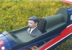
The cockpit/cabin areas of ARTF models are covered too - invariably by moulded 'floor' trays and bubble canopies, or pre-moulded glazing panels. Deal with these items as described in detail in the January 1999 issue of RCM&E magazine. For gawd's sake, don't forget to fit a 'driver' of the Homo-sapien variety in the cockpit or cabin when clear glazing allows an equally clear view inside the model's 'office'! You may get a self-adhesive cockpit 'instrument panel' decal, so put it to good use! When combined with well-painted floor/seat detail, and an appropriately-styled pilot figure, the overall effect can set your ARTF apart from all the other clones! I like Humbrol matt enamels best for brush-painting the cockpit interior, and for applying that 'fly-boy' make-up!
See a Shrink!!
Rippled ARTF model covering is indeed an uninspiring sight! Here's how I cope with this 'bad patch' which usually results from storage temperature variations.
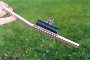
The tough 'Fablon'-like self-adhesive covering material so often encountered seems to tolerate heat manfully, so I blast it with the full-strength setting of my heat gun, to 'iron out' any problematic skin wrinkles. (If only this worked with humans!) This type of film has a sluggish shrink rate so, even when minor wrinkles need doing, the duration of the heating time needed to prompt a 'reaction' causes the entire 'host area' to crinkle up also! I therefore 'go with the wind' and re-shrink the entire host panel within which the initial wrinkles were contained. Film-covered open frames seem to tighten up faster than sheeted areas I find. It's also possible to partly cure mildly warped built-up wing and tail panels if they're bent against the twist by a helper as you do the 'blow-drying'! The technique doesn't always work though - it all depends on the rigidity of the underlying framework.
Wrinkled covering film over a foam skin underlay is thankfully less common as both materials bond fairly tenaciously. Just as well, as there's a very fine line between adequate film crinkle shrinkage and total foam layer burnout! Short, sharp, full-strength blasts, held for a couple of seconds with the gun nozzle just over the crease, before wafting the appliance back-and-forth further away from the covering, is the delicate balance required for troublesome foam-bedded film. Go easy, or you'll be 'foaming' at the mouth…
The heat gun travel pattern, blast intensity, blast duration, and distance from the film's surface, are critical judgement calls that decide whether the outcome will be medium, rare, or well-done! Use the heat gun with the nozzle tip-adaptor fitted to control and target the 'balmy breeze' more effectively. Practise on some unimportant inconspicuous small area first, before treating that larger important expanse.
Rip Off!!
Covering film stuck over ARTF component gluing areas can be tackled in a couple of ways. The film can be roughened with 180-grit glass-paper where non-critical cosmetic items stick directly on - but the film definitely needs removing from the horizontal/vertical tail/fuselage interfaces if subsequent in-flight action isn't to end in a 'tail of woe'!
This film-peeling exercise demands the very sharpest of scalpel blades, and the very lightest of handiwork, to avoid scoring the wood beneath. Mark the film's cut-lines about 1/16" within the fuselage tail-seat area to stop bare wood showing up later on. Cut the film through in several ultra-delicate blade runs. When 99.99% of the way through, lift off one end-corner edge of the film and peel it back on itself to fully sever the now weakened cut-lines. You'll probably have to re-score portions of the cut-lines to get the film off properly. What can I say? It's a bitch job!
Transferall.
Getting those sticky-back decals on the airframe can be a 'touch' tricky! Personally, I do it either totally dry - or, with some added lubrication…
I cut very closely around the design (right against the edges) with sharp scissors and/or a scalpel, then I peel back about 1/2" of the backing paper at such an angle that it will be 'pullable' with the design in place as intended. I align the main body of the design, then fix it with fingertip-pressure on that small exposed sticky portion. With the main decal area lined-up, and the whole thing pulled taut against the anchored sticky patch, I carefully pull the backing paper out from underneath, thus gradually exposing more adhesive area in the process.
Decal misalignment, because of backing paper-removal disruption, can be an annoying problem, so I often reveal more adhesive area to begin with. On occasions I've exposed almost half of the available adhesive area before 'hovering' the decal over its intended location. With the larger area adhered lightly (work from the centre outwards), removing the remaining backing paper causes less disturbance. I may entirely remove small decals from their backing sheet, and stick 'em on the tip of a scalpel blade for alignment purposes, before pressing down from the centre-point outwards, to avoid air bubbles forming.
Totally removing the backing paper, then applying the sopping-wet design on a soapy water solution sponged onto the model's skin, is another way of getting total decal alignment satisfaction. Remove the decal from its backing sheet 'under-water' in a basin first to ensure thorough adhesive disablement. Most good quality ARTF model decals will happily slide about, guided by a scalpel tip, until they're aligned correctly. Then they'll stick well once excess water has been soaked up by a wad of tissue paper. Some ARTF decals hate water, so the 'dry-fixing' routine is a must in these cases.
Self-adhesive decals may not be fuel proof. I coat 'em with clear polyurethane varnish, as it doesn't attack the pigments used.
Skin Fix!!
Repairing ARTF model coverings is a terrible task! I've used Solarfilm/Solartrim with reasonable success (see 'Wing Waffle' article, also on this site), having first etched the tear edges with 'Prymol'. When well bonded and shrunk tight the tear was sealed, but the colour-match was crap! It's about time that instant aeroplane manufacturers introduced self-stick 'repair sheets' of compatible colour-coordinated film, to nurse their all-too-easily-punctured creations back to health!
Damaged 'foamies' can have polystyrene foam chunks epoxied into the wounded component, then surface-sanding maintains the outer skin contours. Foam food trays, cut into patches and placed on thin ply locating tabs glued beneath the skin-break edges, can be knitted into place over built-up ARTF models' film/foam skin holes. Don't forget - only use epoxy or PVA for foam repairs!
A Quick Get Away!!
If you've assembled your ARTF model correctly, installed all the bits and pieces carefully, and balanced it as prescribed (Ripmax 'granulated lead', set in epoxy, is an excellent ballasting medium), you should have a fab flying machine. Assuming you are willing to sacrifice your 'individuality of finish' for rapid in-flight thrills, then this type of model will allow you to learn to fly R/C planes, progress to aerobatics (both 'sport'- and 'contest'-class), and even some semi-scale action can be had from several ARTF kit makers. Whilst I personally remain cold on the 'buy today/fly tomorrow' concept, with a little dedication, and a reasonable quality kit, you'll enjoy potentially huge amounts of flying fun for the relatively short 'put it together' time involved. And, for many 'New Age' hobbyists, that's the name of the model flying game!
See you at the flying field!
Picture Captions.
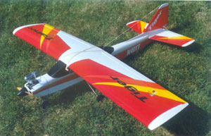
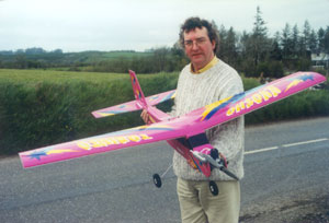
1: Do you think that ARTF models are a piece of cake to assemble and fly? Think again! Here's a prime example of how not to put such a machine together! Gerard spent the best part of a month rebuilding this cocked-up Thunder Tiger 'Tiger Trainer 40' for its owner who got it all badly wrong! The model flew okay after the refurbishment.
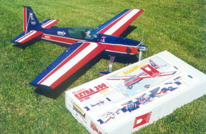
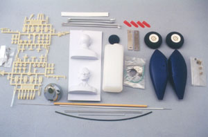
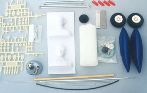
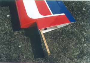
2: Nice box, nice model! What about the stages in between? All is revealed here…
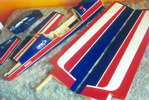
3: Typical ARTF model kit airframe components. Are you putting them all together in the best possible manner?
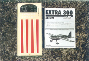
4: The assembly manual and decal sheet pictured here were both good quality items. Many ARTF kits offer less inspiring materials!
5-6: The basic airframe is only as good as the accessories that keep it flying! Check this area carefully before splurging.
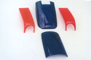
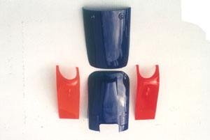
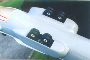
7-10: Self-adhesive trim tape is frequently used to disguise joints on ARTF models. Guess where the breaks are on this cowl?
11: Treat lifting decal edges as described here. This example has yet to be dealt with!
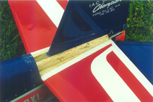
12: Be wary of suspect airframe joints whilst purchasing your ARTF kit. This trouble-spot was repaired with epoxy.
13-18: Get those wing panels joined as advised and you'll soon be ready to roll - literally!
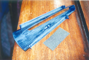
19-21: A good solid tail unit results if you strengthen the fin base as shown. Note the well sanded gluing areas.
22: An example of enlightened ARTF fuel tank design! The circular foam collar both protects the tank front against crushing and aligns its passage through the firewall at the same time.
23: Feeney's always been a bit kinky when it comes to bending fuel tank metal pipes! Now that's a thing of the past, as these tube bending springs enable him to 'go around the bend' in the nicest possible way! Order these bending springs through your local model shop under the 'K&S' label.
24: A spatted undercarriage looks great on many ARTF aircraft designs. The dural or wire-frame landing gear needs some care to fit, and those spats can be vulnerable.
25: Make sure your ARTF tail-dragger has a well-supported tail-wheel to minimise rudder hinge-line strain!
26: ARTF aircraft can take both fixed and retractable landing gear. Only practical operation will reveal whether or not the structure is tough enough to endure the loads imposed…
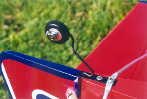
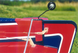
27: Plastic fairings make ARTF model pushrod exits and rear ends look neat. They come in all shapes and sizes. Here, the tail control links and the sternpost/tailwheel mount areas are streamlined nicely.
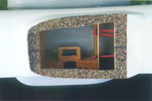
28-29: Get that instant aeroplane radio installation sorted properly! This is Colm Kelly's 'Transall C-160' radio bay all ready to accept the important electronic bits.
30: Seems like a nice boy! Don't omit some basic cockpit/cabin detail in your ARTF. Feeney always employs a Williams Brothers' 'split-personality' to steer his miniature aircraft…
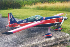
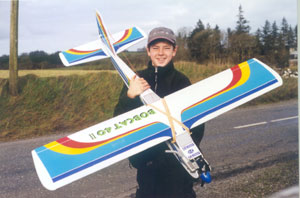
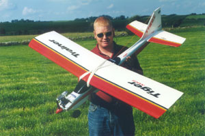
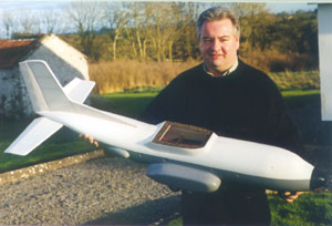
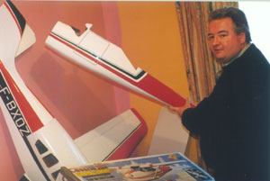
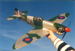
31-36: The sky's the limit with R/C ARTF model aircraft! Trainers, aerobatic hot-ships, and scale-types, are all available for your enjoyment. But, check quality levels before splurging, to ensure that you've got the best kit available!
 |
 |
|
1
|
2
|
 |
 |
|
3
|
4
|
 |
 |
|
5
|
6
|
 |
 |
|
7
|
8
|
 |
 |
|
9
|
10
|
 |
 |
|
11
|
12
|
 |
 |
|
13
|
14
|
 |
 |
|
15
|
16
|
 |
 |
|
17
|
18
|
 |
 |
|
19
|
20
|
 |
 |
|
21
|
22
|
 |
 |
|
23
|
24
|
 |
 |
|
25
|
26
|
 |
 |
|
27
|
28
|
 |
 |
|
29
|
30
|
 |
 |
|
31
|
32
|
 |
 |
|
33
|
34
|
 |
 |
|
35
|
36
|
![]() Back to Home page
Back to Home page