
Legging It!
Fitting
Robart Dummy Oleo Legs to your Model?
Allow Gerard to take you through the proceedure as painlessly as possible...
Robart scale landing gear 'strut covers' have been available for ages but I must admit that I'd never given 'em much attention up until the recent past. The latest 'Feeney Flier' most definitely demanded disguised piano wire undercarriage legs however, and these Stateside items seemed the ideal choice. Although not specifically reproducing any full-size aircraft legs in particular, they are eminently suitable for dressing up sport-scale 'lightplane' and 'fighter' designs, and with a bit of TLC they can look most realistic. They certainly transformed the (fixed) 'alighting gear' of my Top Flite Beechcraft 'Bonanza' no end, I must say.
Leg Pulling
The
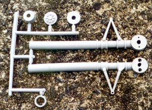
basic oleo 'facade' components arrive poly-bagged on a sprue, Airfix fashion,
ready to be stuck together. The (injection?) moulding quality is pretty
darn crisp but, as always, it's a good idea to separate the individual
pieces carefully, making sure that all sprue 'attachment points' and surplus
flashing are removed cleanly. A very sharp Number 11 scalpel or keen single-edge
razor blade are both ideal plastic incising/cleaning-up tools in the pre-assembly
preparation routine. It's also prudent to dry-assemble the oleo units
over the model's wire legs just to precisely ascertain the component fits
- and to see if any 'non-standard' cutting/trimming is needed. If trimming
is required, it'll most likely involve shortening the actual vertical
oleo tube height to suit short wire legs. This is easily done with a razor
saw, followed by fine-sanding to clean up the plastic edge prior to eventually
closing the oleo tops with the capping pieces provided.
When sanding the plastic material, either after component sprue separation
or after oleo unit assembly, use fine grade wet 'n' dry paper (used either
wet or dry!) in the 350-800 grit range. Paper grades coarser than this
will cause the plastic to become 'hairy' rather than actually smoothing
it.
The Leg Bone connected to.....
The oleo units are comprised of six principle parts. Each main upright leg is split vertically; these half-shells encapsulate the wire leg from either side with the actual joint lines facing the front and rear. The oleo circular wheel bases are pre-drilled to allow the wire axle to poke through; the holes may need enlarging to suit larger gauge wire legs. The oleo halves partially clasp together by means of tiny pre-moulded male/female studs located inside each triangular 'torque-link' projection; these snap-keepers are backed up by teeny-weeny machine screws going through the circular axle bases, which are then hidden by dummy capping discs. The dummy capping discs locate using a push-fit action on the oleo axle base opposite the fitted wheel. The hollow wing- (or fuselage-) facing oleo tubes are blocked off by neat cups/caps after a 'retaining ring' has been slipped halfway down the oleo leg to stabilise the assembled component. It would almost be possible to leave the units dry-fitted only, but ideally they should be properly glued together…
Sole Mate!
Oleo
fitting and assembly goes like this: First, accurately finalise the basic
fitting of the model's wire legs in place on the airframe using saddle
clamps, minus the dummy oleos. Remove the legs again to fit the oleos
before final leg attachment takes place. Feed the wire axle through the
respective half-shell base first, ensuring the wire fits the vertical
half-groove snugly at the same time. If the base hole needs enlarging,
ensure that it's just big enough to allow a smooth axle penetration; a
drill bit followed by a round file (or glass-paper wrapped around a 1/8"
hardwood dowel) is useful for this work. Now, the other half-shell is
coaxed into place. Because of the pre-moulded locator pegs, a fairly accurate
'snap-fit' of the two oleo halves is easily achieved. At this stage, the
alignment ring and wing/fuselage-meeting end cap parts are test-fitted
again. With wing-mounted wire legs, you may need to enlarge the oleo end
cap hole slightly to enable it to slide around the various sharp bends.
I managed okay though 'as per' - on the Bonanza, at least.
When all fits are deemed satisfactory, the end cap and alignment ring
are removed again; now it's time to permanently join those main oleo halves
in-situ on the wire leg. This can be done by simply wicking thin cyano
into the joint lines using a pointy applicator tip - or glue can be applied
(Airfix-fashion again) to the separated half-shell joining flanges before
pressing accurately together. I've tried both gluing methods and slightly
prefer the 'wicking' approach because the half-shell alignment can be
pre-tweaked in this instance. The disadvantage with the cyano wicking
method is that some areas of the half-shell contact are tighter than others
resulting in patchy cyano penetration. The 'glue then bring together'
approach could lead to mildly misaligned parts if fast cyano was used;
if trying this 'meeting up' gluing approach, Airfix polystyrene model
cement or slow cyano would be the better gluing choice.
When the oleo shells have been glued together, those axle base fixing
screws can be fully tightened up. I left these screws slightly loose during
gluing to allow for the cyano 'seepage' factor before fully tightening
home - but you could rely on just the screw hold to grip this area with
the glue only applied further up the oleo if you wished.
At this stage, no matter how neatly you've joined the oleo half-shells,
some slight moulding misalignment will be evident - mostly around the
protruding circular flanges. Just trim/fine-sand the proud areas back
to harmonise the lines. I also noticed prominent joint line cracks on
some areas; you could try filling the gaps with 'Elastic Plastic Padding'
or similar 'car body' filler. However, I found all of this stuff fell
out again when dry, so a good fine-sanding using 400-grit glass-paper
on a miniature sanding block and/or impact-glued to thin ply works best
to camouflage the visible joint areas. There is another way of disguising
these cracks - see later.
The alignment ring and end cap bits (left a loose fit on the wire leg
during oleo attachment) are now finally slid one final time into position.
Slip the ring halfway down into place first, followed by the end cap.
These items are very easily glued in-situ with thin cyano.
My legs needed extra clamping with Bulldog clips either side of the triangular
torque arm projections, whilst thin cyano bonded the internal connecting
framework together. Minus clamping, the internal pre-moulded plastic 'ribs'
won't meet up in this area. This ain't serious structurally - but it doesn't
look good!
Final assembly involves cyanoing the 'hub cap' and 'wheel-spacer' discs
in place either side of the oleo base. The hub cap disc (actually positioned
diametrically opposed to the fitted wheel - and not even on the wheel
at all!) could almost be left a friction push-fit - but I preferred to
get fully 'stuck in' for added security! The plastic wheel spacer disc
can be used instead of a metal collet 'twixt oleo base and wheel inside
face, but I also used standard metal collets either side of my installed
wheels out of personal preference.
That's about it with the basic assembly; now comes the decoration…
Fancy Footwork!
It's
best to spray the assembled oleo units using the masked off undercarriage
wires, in conjunction with Bulldog clips, as stabilisers. I employed Flair
'Spectrum' matt dark grey and a few coats saw the units looking much more
solid. I didn't bother with primer and all seems fine - but it would be
no harm to prime the units providing the primer, paint and plastic are
all compatible.
The metallic 'telescopic shock absorber' areas, which are usually bright
chrome on the full-size aircraft, presented the biggest headache to get
right. I started with brushed on Humbrol silver which, being rather old,
went on with a yucky 'textured' finish. Some new stuff, applied with a
small artist's sable, went on a bit better - but I was acutely aware of
this product's non-existent fuel resistance, so one just wasn't happy!
(Any attempt to fuel proof Humbrol silver will turn it into a grey sludge!)
Then one heeded Robart's suggestion to use self-adhesive chrome trim sheet
on these areas. Very nice, but would it be available? Luckily, Flair's
'Aluclad' was…
Foiled Again!
Aluclad
is an ultra-thin self-adhesive foil which, with care (and a clinically
smooth basic airframe finish!), can be used to cover entire 'solid-surface'
model airframes in sections. (I dread to think of the cost, though!) After
an initial brief examination, it seemed ideally suited to the task of
representing the chrome telescoping tubes of full-size aircraft undercarriage
legs - and it sure came to the rescue with the 'Feeney Zone' Bonanza!
Basically, strips the depth of each visible shock absorber section were
cut out using an extremely sharp scalpel. These strips were then tailored
to wrap around the oleo and butt-join at the rear out-of-sight. Placement
is not critical, as the adhesive doesn't grip too severely at first. However,
it's easy to crease the foil by heavy-handed initial removal from its
backing sheet and/or during repositioning attempts on the component being
covered. It's wise to have oodles of foil strips standing by if (when!)
cock-ups occur.
The oleo strips went on quite easily; an alternating pressing motion from
the first (central) contact point around towards the rear butt-joining
'meet-up' point each side worked best for me. Various pieces of scrap
hardwood strip were employed to press the foil all over and especially
into tight corners - it's surprising how well it 'moulds' into the nether
regions one is happy to report! Excess foil is easily cut in-situ with
a very keen Number 11 scalpel blade; tweezers are useful for gripping
and plucking the severed foil offcuts.
I must say, I wish I had 'foiled' these areas right from the start for
a smoother finish - but ya live and learn! I'd strongly advise readers
to simulate these areas using Aluclad or similar; this is best applied
after simply spraying the entire oleo unit in one colour first. The triangular
torque arm projections could then be left in the 'background colour' or
painted silver as I did. Using self-adhesive foil on all the cylindrical
oleo areas would also be possible - doing this would hide those (sanded)
joint-lines more effectively too!
Walk Away!
The assembled/painted oleo units are now ready to go on yer model by finally re-clamping the wire legs in place. Remember, during the initial dry-fitting stage, not to place any retaining saddle clamps too close to the undercarriage vertical 'groundborne' leg as subsequent clamp tightening might cause screwdriver clashing on the oleo unit! Whether your model is a 'serious' scale ship or a fun-scale/sports job, these items will really smarten the aeroplane up. Robart's oleo units are available in 'large' and 'small' sizes and in both 'main' and 'noseleg' format, so you're spoilt for choice. I've just ordered the noseleg version, also for the Bonanza, so one can look forward to yet more exciting leg thrills in due course! Be still, my beating undercart!!!
 |
 |
|
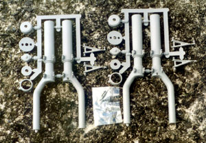
The
various components for Robarts dummy oleo legs, available in assorted
size "main" and "noseleg"
format, arrive nicely presented in poly bags. The bits have been taken out here! |
 |
 |
|
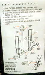
Heres
how the various bits go together. |
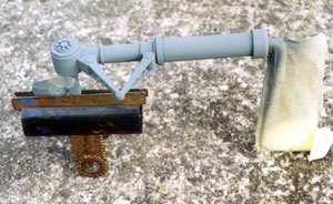
The
assembled leg being sprayed matt dark grey.Note masked off wire.
|
 |
 |
|
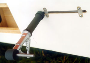
Make
sure the undercarriage wire retaining saddle clamps ain't too close
to the dummy oleos or you could suffer "scratched legs"!
Guess how Feeney found that out?!
|
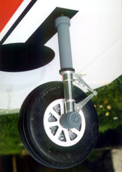
The
finished oleo on Gerards Top Flight Bonanza certainly looks the
part. Note the Aluclad foil covered areas. Dummy "undercarriage
doors" made from thin ply have since been added to complete
the effect (wheel bay opening is cut from solarfilm)
|