ALL RIGHT AT THE BACK? AVOID A 'BUM' DEAL WITH GERARD FEENEY!
One has
been giving much article attention in this web site to the subject of wing
details - now, it's time that the tail got a look in. So, let's get that rear-end
in shape 'Feeney Zone' fashion without further delay…
SLAB STAB
Balsa all-sheet tail surfaces are by far the easiest airframe stabilisation
components to assemble - basically, it's just a matter of butt-gluing the
full complement of sheet slabs together. However, some care and attention
to detail is still prudent to ensure optimum results.
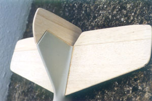
Ensure that all the sheet parts are of equal sectional thickness. With pre-cut kit tail components, slight wood thickness variation often occurs; cutting the bits yourself will of course ensure strict quality control! Parts varying in thickness by about 1/32" are okay - just glue the slimmer sheets together sectionally central relative to the thicker sheets. Larger material variances will usually require a complete replacement of the thinner stock. Cross-grain tips are always a good idea on all-sheet tails to discourage chord-wise warping tendencies; however, many kit designs omit this feature. If designing your own models, I'd suggest that separate tips be added. Inset balsa rectangles, with the grain running chord-wise, grafted into matching cut-outs in the tail surfaces, are also good anti-warp features on OD models.
Hardwood spars are included on some all-sheet tails for even greater strength. These are best glued to one of the span-wise sheet slabs before making up the whole tail; subsequent part joining is then much easier. Hardwood tail spars should never actually reach the tips because they prevent easy edge shaping. If this problem is encountered, shorten the hardwood spar by about one inch at each tip and replace the lost spar material with scrap balsa.
A sandable aliphatic or white PVA glue, used fairly sparingly, is best for gluing the sheet pieces together. I usually do the job in mid-air, using strips of Sellotape and edge pins to first hold the required alignments, then to 'pull-clamp' at regular intervals along the joints. Invariably, adhesive will ooze out - this is why the minimum amount is called for. Glue emissions beneath the tape strips will need clearing away by removing the tape and wiping the glue off with a damp cloth or tissue. This is followed by the application of new tape strips as required. Ensure that the tape strips are stuck on each side of the balsa bits with 'symmetrical' placement; this way, chord-wise twists are avoided. Cyano can also stick all-sheet tails together, but precise fits are crucial. A thick slow-acting cyano, and hand-holding the parts instead of taping, may be the best bet in this instance.
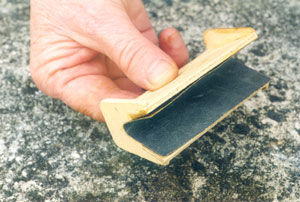
Finish-sanding all-sheet tails is simplicity itself. A good going over with 180-grit glass-paper on a sanding block blends in all the individual pieces and minimises joint lines; a razor plane followed by block-sanding will smooth the corner edges too. Fine glass-paper, going as smooth as 400-800-grit, will really bring 'em up silky smooth. Carl Goldberg scale kits include a very 'handy' ply-manufactured sanding jig, into which glass-paper is stuck, to nicely contour the leading edges and tips of 1/4" thick wooden tailplanes at the initial rough-sanding stage. I've been using mine for the past 12 years on many models with flat plate section tails - both solid and built-up. A similar sanding jig could easily be made from liteply to suit thicker section tails. (Don't glue the glass-paper permanently in place; 'push-fit' pressure is sufficient to retain it, and worn paper can then be easily changed as required.)
FILL THE FRAME…
Built-up flat plate section strip wood tails are simple creatures to create. These comprise perimeter 'outline' edge strips pinned to the plan, within which a solid sheet 'centre section' tail seat portion and chord-wise-oriented parallel/diagonal interior 'strip rib panel fillers' reside. Hardwood sub-spars may be placed in behind the leading edge strips and/or in front of the trailing edge strips before the centre section tail seat mount is added, for additional torsional strength.
Assembly is so simple - it's just a matter of pinning the various strip/sheet pieces in place over the drawing. Getting good edge fits is the key to success, and here it's better to have mildly over-size parts which can be block-sanded at the edges for a really precise fit. An ultra-sharp single-edge razor blade is ideally suited to cutting the thin-section tailplane 'area filling' strip pieces to fit - especially if they're installed in a 'repeating V' formation. I normally put the tail seat sheet on the plan first, followed by the leading/trailing edges and tip strips. The thin-section strip ribs now link the leading and trailing edges, and any corner gussets and hinge mounting strengtheners are also added at this stage. If sub-spars are employed, these can be pre-glued to the leading and/or trailing edge strips before pinning to the plan.
I favour PVA for this type of assembly, as 'tweaking' time is available and excess glue is easily wiped away with a scrap hard balsa spatula. If fits are very good, cyano will work well too. Finish-sanding is as advised for all-sheet tail surfaces.
Built-up framework tails can also be skinned with edge-joined thin sheet balsa. This produces a very rigid unit; just ensure that the frame is on a true surface as each side is skinned - otherwise, a permanent twist will be built in! Evo-Stik impact adhesive is my own personal favourite glue for bonding skins to frame tails; leave the sheeting somewhat over-size, then cut to suit the tail outlines once attached. Profiling leading edges where impact-glued outer skinning is fastened can be tricky, as the cured rubbery adhesive can tear away under razor plane and glass-paper attack! I normally use slow cyano for the 'outer edge' areas, in concert with the contact glue, for best shaping results.
'BUTT' JOINTS!
Built-up aerofoil section tails are usually constructed directly over the plans, just like mini wing panels. An interlocking spar/rib assembly with centre section horizontal tail seat structure built-in takes leading and trailing edge strips as appropriate. Block or built-up tips, internal gussets and hinge mounting blocks then join in the fun! Depending on the tail section, the spars can be added before or after the ribs go on. Symmetrical section tail ribs in kit models feature lower surface jigging tabs which are cut off after removal from the board. Plan-built designs also use such tabs; though strip packing pieces are also employed for the same job. If part fits are close, cyano can be used to 'fuse' together the dry-assembled pin-held structure over the plan. If fits are sloppy, it's better to use PVA and pins to construct the fixture.
Aerofoil section tails are frequently partially or fully sheeted. In either scenario, PVA and pins or impact adhesive with slow cyano at the outer edges is the way to go when tackling the skin placement. With either sheeting arrangement, the tail surfaces obviously have to be skinned on the 'outside world'-facing side first while still attached to the building board; the opposite side is then skinned after removing the components from the bench. Do ensure that modelling pin removal is possible after the tail bits have been initially skinned on the board - if access is poor, a screwdriver (and/or Valium!) may be required to manoeuvre/pry the anchoring pins free
'CORE' BLIMEY!
The 'sheet core' tail surface produces what looks like an open frame structure with hidden inner strength! Leading/trailing edges/tips/hinge blocks, and all 'rib/spar' detail strips, are glued on each side of thin central sheet cores cut to the shapes of the horizontal and vertical tail profiles. The structural 'façade' details are then finish-sanded to section on each side of the central core sheet giving aerofoil or flat plate section tail surfaces, depending on the half-rib/perimeter strip configurations. Strong, light, and warp-resistant components are the final result.
'TV' TIMES
'T'- and 'V'-tails are constructed in the same manner as conventional stabilisers - it's really only the 'model attachment' aspect that sets 'em apart!
A T-tail is basically a horizontal tail sitting on top of a fin. Regardless of the fuselage and fin material, some sort of fin-top mounting platform is required. On timber fins, this can be a ply plate stabilised by triangular stock gussets or similar; moulded hollow fins will most likely employ integral glassed-in mounting plates of wood, GRP, plastic or metal. Depending on the model design, either glue or bolts will secure the horizontal tail.
V-tail panels usually get linked by ply 'dihedral braces' which feed into root leading/trailing edge slots - in a similar manner to wing panels. The braces in turn anchor inside the fuselage tail seat opening. Usually, the braces are built into the fuselage rear-end first, then the separate tail halves are mated on in-situ. On many occasions, the individual tail halves don't actually join root-to-root - the linking braces along with the tail seat contact provides the necessary rigidity/alignment. Other times, the centre joint can be filled in with scrap wood and beefed-up with glass cloth and epoxy. V-tails are usually built into the fuselage and the rear fuselage sheeting is cut to suit as you proceed; this needs care to get neat! Removable V-tails on gliders and sailplanes are held by central anchor bolts driving into spiked nuts in the fuselage tail seat.
T- and V-tail configurations demand special linkage and control surface mixing considerations. T-tails that are 'all-moving' or with separate control surfaces use either curved snakes or large bellcranks within the fin, in-lieu with pushrods/kwik-links, to connect up/move the control surfaces. V-tails use either snakes or conventional pushrod control surface hook-ups, driven through an electronic tranny mixer or an old-fashioned mechanical mixer.
MOVING TAILS
An 'all-flying' tail is an elevator-less horizontal stab which pivots at the 'mainspar' position to give pitch control. These units can be constructed in any of the ways described for conventional tails, but the 'pivoting' hardware must be installed within the root centre section, so that it can connect up to the linkage contained within the fin. Glider all-flying tails are often removable halves which plug on to wire joiners protruding from the installed fin bellcrank unit.
BRACE YOURSELF!
Sometimes, model tails feature either dummy or functional bracing wires/struts linking the horizontal tail to the fin and fuselage sides.
Dummy rigging is just 'shirring elastic' (available in haberdashery shops) which is fed through short plastic tubes installed in the tail surfaces. The elastic cord ends can then be knotted together at the fin top and/or cyanoed at all the tube locations.
Functional bracing usually takes the form of cut-to-length alloy tubes, which are flattened and drilled at the ends. Small bolts going through tube-bushed holes in the tail surfaces, and screws or bolts going through the rear fuselage, then 'clamp' the flattened tube ends to the fin/tailplane/fuselage surfaces creating a rigid 'triangulated' rear end. Needless to say, precise alloy tube cutting/shaping/drilling is vital for proper tailplane/fuselage alignment. All the tail 'bolt pass-through' points need strengthening with inset ply plates or small hardwood blocks during the airframe build. Wait until these tail surface 'hard-points' are installed before drilling for the 'through-tail' plastic tubes. Drill the alloy tube ends first, and then use 'em to locate the bolt-guiding plastic tube-lined hole positions in-situ after the tail parts have been permanently glued to the fuselage.
SKIN HEAD
Veneer/balsa-skinned foam core tail surfaces are simple to manage. Once the balsa leading/trailing edge/tip segments have been added (if needed), a thorough sanding will see the components ready for covering and model attachment. Of course, the horizontal tail panel halves need epoxying together, but this is a straightforward job.
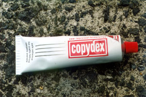
One mustn't forget hot wire-cut foam tail components which require balsa or veneer skinning by the modellist him/herself! Copydex impact adhesive is first applied to the foam tail cores and the slightly over-size builder-manufactured made-up balsa (or obeche veneer) skins. A small amount of coloured food dye added to the Copydex will render it more visible during application over white foam areas. When the Copydex is dry, the skins/foam components are gently and methodically pressed together, being careful to keep each tail panel flat on the board as pressing occurs. Sitting the tail bits on their 'sliced apart' parent foam blocks whilst doing the skinning job provides excellent stability.
The Horizontal tail is done in half-panels, doing a bottom/top panel at a time. The fin is just done one side at a time. Press the skins in place at the point of maximum sectional thickness and work fore/aft towards the leading and trailing edges. You could go from the trailing edge forwards also. Take it carefully - remember, you get only one chance of achieving correct alignment, so have those skins well over-size! The leading/trailing edges and tip blocks are glued on when the skin has been trimmed to shape.
FOAM FIX
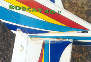
Electric-powered foam model tails normally just require the pre-moulded parts to be epoxied to the fuselage. Damage to foam tails is easily treated with epoxy. I recently used half-hour epoxy to butt-join a nasty chord-wise fracture on a 'Pico-Cub' horizontal stab. After wiping away excess glue, and simply leaving the tail on a flat surface as the glue cured, a perfect repair ensued.
A TWIST IN THE TAIL
The moving control surfaces of tails can be of solid or framework construction. Usually the 'parent' and moving tail surfaces share a common constructional theme; but frequently built-up control surfaces are teamed with solid fixed surfaces, and vice-versa.
On scalish built-up aerofoil section tails, the waggly bits are often built as part of the main structure, then separated along the pre-installed balsa strip hinge lines. Additional balsa strip capping, glued to the control surface leading edges after removal, enables chamfering to take place for deflection purposes. Built-up control surfaces will also see hinge blocks installed early on. The simpler flat-plate solid and built-up tails get the wiggly bits hung on the ends after each component is finished separately. Skinned foam tails always have ample balsa edge strips for hinge anchorage; here, the wobbly bits are 'outlined' with stout balsa strip whilst the main tail is being completed. 'Foamie' model aircraft tails almost exclusively utilise factory-produced full-length 'top hinges' which are machined directly from the foam surfaces themselves. Strips of strong clear self-adhesive tape are recommended as hinge line reinforcement aids in this case. Specially designed plastic hinges which epoxy into pre-cut slots are also used with foam tail surfaces.
Control surfaces on any tail type (excluding pre-moulded foamies) can be tack-glued in place whilst finish-sanding the main components; this action provides nicely harmonised fixed and moving surfaces later. Sheeted foam tails always arrive with factory-cut control surfaces that match the fixed surfaces nicely.
Regardless of the type of tail construction, it's always wise to add control surface horn mounting ply plates during the build. If doing an OD, these should be mandatory; if doing a kit model minus these items - add 'em! As one has said before: the ply horn mounting plates can be recessed into solid sheet or foam surfaces during the build, or thin ply patches can be glued each side of a control surface on the outside skin after the build. Sanded 1/16" Perspex sheet, stuck in place with R/C Modeller's Glue or cyano, also provides adequate horn mounting/anti-crush control surface support. Electric foam models are the exception again; here, the control horns epoxy into factory-moulded recesses.
TAIL LIGHT?
Murphy's and Sod's Law frequently decrees that sheet balsa supplied in kits for all-sheet tail assembly is often rock hard and heavy! If this is the case, it's probably a sensible idea to replace the wood entirely, but on many occasions, the material can be salvaged by cutting strategically placed lightening holes.
In the past, I've used an OLFA 'compass cutter' device (designed for cutting varying-diameter paper circles and frequently employed for Solarfilm/Solartrim disc manufacture) to remove wood. This works best with sheet tails in the 1/8" thick category; it struggles a bit on ¼" wood! Cutting holes with such a tool is best accomplished with successive light runs; trying to dig the blade in through the wood will cause complete blade stalling - and blade movement on its fixing point. Anchor the compass cutter spike in a piece of thin ply taped to the balsa at each hole centre location; without this, the tool will wander as the balsa is cut.
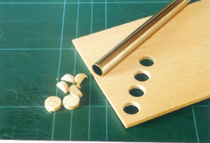
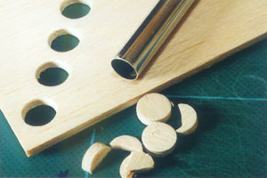
Another ultra-simple sheet tail 'bulk removal' route is to mark out the holes using coins or similar suitable-sized circular templates. The outlines are drilled through with a 1/16" bit, and a sharp scalpel blade then removes the perforated lightening holes. Drill slightly inside each marked-out hole disc; this allows the ragged edges to be fine-sanded. Some 180-grit glass-paper wrapped around a circular sanding block (a broom handle or hardwood dowel offcut are good), or a Perma-Grit tool, cleans up the hole edges nicely. With care, this method produces really crisply formed lightening holes.
A faster hole removal method is to use a Dremel tool to drill the marked circle edges; the sanding drum attachment is then recruited to clean up the scalpel-removed holes in double-quick time.
A sharpened length of tranny aerial offcut is also ideal for making thin-section tailplanes more 'holy'! The tubular 'cutting rim' must be kept keen by paring its inner edge with an angled Number 11 scalpel blade.
A 'hole saw' (I hope I've got its name correct) could also be used with care to perforate hard sheet tails. These tools look like deep saw blades wrapped into cylindrical shapes with the teeth forming a hollow rotating cutting drum, and they are available in differing diameters from good hardware/DIY shops. The resultant 'boring saw' (which is fixed to, and rotates on, a special central drill bit) fits into an electric power drill chuck, and the desired hole size can then be excavated very rapidly indeed. One needs to be careful here, as these things are for 'full-size' domestic DIY jobs and, unless you start drilling easily, balsa damage could result! The sawn holes will definitely need some edge-cleaning with 180-grit glass-paper on a round sanding block.
Strength combined with lightness are desirable tail surface characteristics. So, with care, lightening holes can be 'inserted' into most normally-constructed tailplanes without fear of compromised structural integrity - and with all the benefits of easy model balancing to enjoy later on!
BACK OFF?
Aligning flying model aircraft tail surfaces is surely the bane of every modeller's life! I can honestly say that, since I started building R/C aeroplanes in 1975, I've never once achieved a truly 100% straight tail/fuselage/wing relationship - but one lives in hope! The following method, done with care, will help achieve a reasonably straight airframe/tail mating. Remember, wooden airframe models must be built accurately from the beginning, with no 'banana' fuselages! Hopefully, 'pre-formed' models will have intrinsically accurate airframe parts to start with!
After checking that the wings sit level on the fuselage wing seat, looking from the front or rear of the model, fix the wings to the fuselage using either rubber bands/dowels or bolts as recommended. If the wings sit wun-wing-low, sand the wing seat as necessary.
Only secure the fuselage/wings properly when the distance between each wing tip rear end (or other fixed tip reference point) and each side of the rear fuselage at the sternpost position (or the sternpost centreline) is as closely matched as possible. Try to achieve matching wing tip/rear fuselage end measurements that deviate by no more than 1/8" - less if possible. I use a steel retractable tape measure for this job; you also need a helper to hold one end of the tape measure firm as you strive for equally-spaced dimensions!
With the wings and fuselage locked together as accurately as possible, it's time to get the tail alignment sorted. Obviously, the object of the exercise is to align the tail as accurately as possible with the other airframe components both in plan- and front-/rear-views. The first exercise is entirely a dry-fitting routine to eliminate misalignments and to mark the optimised fuselage/tail gluing guidance lines.
Test-fit the horizontal tail (assuming a 'conventional tail' layout) first. Mark a centreline on the top and bottom of the tail centre section; this is used to establish the correct plan-view alignment relative to the wing/fuselage combo. When the horizontal tail looks well placed, a single modelling pin driven into the mid-chord point through the tail seat holds it lightly. If no tail seat sheeting exists inside the fuselage, spot-glue some scrap wood temporarily until the tailplane 'marking-out' process is finished. More pins, placed along the tail chord as needed, provide greater (but easily moved) tail anchorage. Copious 'eyeballing' from all angles now helps determine the degree of actual misalignment, and adjustments can be made as follows…
To establish a precise horizontal tail plan-view/fuselage centreline alignment, take a measurement from the elevator hinge line at a fixed outboard point each side near the tips to a centreline drawn on the firewall top or a front cockpit former. A length of non-stretchy string, about one foot longer than the fuselage length, tied to a pin driven into the nose former centreline, is used to do this.
Fold a piece of masking tape (adhesive sides touching) loosely around the string at the approximate 'average' nose-to-tail alignment dimension at the tail end. Mark this point with a Biro line in the middle of the masking tape 'tag'. Slide the Biro-ticked masking tape tag back and forth along the taut string at the tail end, alternating between the right/left-hand tail tip reference points, until the tape mark no longer needs adjusting. A combination of several slight masking tape/tailplane movements will eventually produce an acceptably accurate tailplane/fuselage coupling. Also check from the elevator hinge line tip extremities to the wing trailing edges where the tip junction occurs with the flexible measuring tape.
When the horizontal stab is positioned accurately in plan-view, mark the fuselage lines on its underside, then remove the component prior to gluing it permanently in place. Before removing the dry-fitted horizontal stab, also determine the amount of front/rear-view span-wise alignment adjustment that's required. If badly off, some balsa tail seat slivers may need adding to the fuselage before tail fitting; usually, just strategically positioned light weights persuade the tail to maintain the correct attitude whilst the glue dries. Angled pieces of sheet balsa, moved in or out in a span-wise direction, whilst the model is resting on the bench, also support the lightly weighted down horizontal tail as the glue goes off in a simple but effective manner.
After the horizontal stab has been firmly and accurately bonded to the tail seat using the marked lines for reference, the fin gets stuck in; this is usually less critical. The centreline on the horizontal stab helps fin plan-view fixing - but tailplane and/or fuselage slots usually exist, so one just sticks it in! If pre-cut fin slots are crooked (determined during dry-fitting), some slot edge-trimming will be needed. A flexible tape measure, or Biro-graduated strip of hard balsa, help achieve evenly matched front/rear-view fin tip/stab tip dimensions.
Always
use slow-set epoxy or PVA glue to attach tailplane bits to wooden fuselages;
the crucial importance of adequate juggling time can't be stressed enough!
Moulded fuselages will have either pre-cut or builder-cut moulding slots,
so here the tail bits slide in after fits have been made free-and-easy with
a file and glass-paper; GRP resin, slow epoxy or specialist glues all work
well for sticking in this scenario.
SEAT OF POWER
The gluing areas of tailplanes obviously need to be left uncovered so that the surfaces achieve maximum bond strength to the fuselage. When building models yourself, it's a simple matter to cut the horizontal and vertical tail covering so that it encroaches inside the sticking zones by no more than 1/16". Leaving this small covering overhang ensures that maximum 'bare wood stickability' is achieved whilst glue-line covering gaps are just avoided. Any major unexpected covering gaps that may come into being are easily camouflaged by narrow strips after tailplane attachment is complete.
Tailplanes are usually covered before fuselage attachment, but several model designs use 'built-in' tailplanes that need covering after being bonded to the fuselage. This is no real problem, so long as the covering is cut to suit the various panels before the components are glued together - but actual covering attachment may be ackward when the bulbous fuselage joins in the fun! It helps to first apply narrow ½" covering strips over the tail/fuselage intersections before putting the main covering panels on; this ensures a neat transition and a gap-free finish.
A regular modelling tacking iron and a specialist chisel-tip 'awkward corner' tacking iron are useful for sticking heat-sensitive covering strips in the corners if that's the chosen covering material. Unfortunately, the chisel-tip iron is only available in America and it needs a transformer to work in Europe! Doped airframes almost always get the fuselage/tail bits covered as an assembled unit; however, providing the corner areas are done first with narrow strips, the results can be very satisfactory indeed. Use a piece of hard balsa strip to press doped covering strips into the corners; this avoids covering 'pull away' as the dope dries.
Pre-covered
ARTF model tailplanes can be tricky buggers to sort out! Frequently, the covering
film is applied right over their fuselage attachment areas and it has been
known for beginners to stick the tail bits on using rapid-set epoxy with the
shiny film still in place - with disastrous airborne tail-detaching results!
Removing this heavy-duty film calls for initial marking of the tail gluing
areas. To do this, insert the tail feathers into the fuselage slots and Biro-mark
the fuselage outline on the root areas of the tail film. Now, run over all
those Biro lines with a hideously sharp Number 11 scalpel blade! You'll need
to do several light passes to achieve a clean cut that doesn't score the wood
beneath. Slipping the blade underneath one end corner allows finger-pulling
of the incised film portions in a chord-wise direction and then you're ready
to stick the tail bits to the fuselage as described earlier.
BORDER LINE…
Whether the tail parts are glued on in a covered or uncovered state, excess glue emissions are almost inevitable; needless to say, such gunk rapidly spoils the finish! Avoid this hassle by encasing the tail surface gluing areas (outside the fuselage lines!) with masking tape before fuselage mating occurs. Now, any surplus glue simply ends up on the tape and it can be wiped away with gay abandon or allowed to dry and flaked away as the tape is removed. With film covered non-ARTF models, you may need to lessen the tape adhesion by running your fingers along the adhesive side; this way, the tape won't pull the covering film away as it's being peeled off. This 'protection' method works with all tail configurations.
THE HAPPY COUPLE!
Elevator joiners are made from short lengths of hardwood strip, hardwood dowel or bent up wire. Here are a few things to remember…
When joining elevators with hardwood strip or hardwood dowel, cut the leading edge recess carefully in each balsa elevator half with a sharp scalpel and small plastic set square after Biro-marking the waste areas - assuming the joiner recesses aren't pre-cut. Test fit the joiner strip, using Sellotape, to establish correct span-wise elevator width relative to the tailplane whilst building the model. If elevator halves go beyond the tailplane span with the joiner temporarily taped in place, either shorten the joiner or trim the joiner recess corners in the elevator halves.
Glue the joiner first into one elevator recess with PVA or epoxy, then lightly tape it firm, being careful to wipe away glue runs. Glue the joiner into the opposite elevator recess, tweaking as necessary to ensure straight half alignment. Repeat the joiner taping/glue wiping routine once more. Place the joined elevator unit on a flat surface and allow the adhesive to fully dry. The unit may be lightly weighted or pinned down, but this ain't usually necessary. The elevator unit can be easily centreline-scribed (using a Gloldberg hinge line scriber tool) and leading edge-chamfered with a razor plane when the joiner is firmly stuck.
The junction 'twixt hardwood joiners and elevator halves can be notoriously fragile! I've lost count of the amount of times I've seen elevator halves split away from this point either due to careless build handling or subsequent 'flying field' action! Some thin glass cloth and epoxy applied over these areas gives great durability. Thin 1/32" ply plates, contact-glued to both sides of the elevator halves at the joiner junction points, are also great reinforcement aids. With luck, the control horn(s) can also be mounted on these plates.
On electric-powered foam models, hardwood joiners are often used to connect the pre-moulded elevator halves together. It's not unknown for the factory-routed elevator joiner channels to be over-long span-wise. If this is the case, simply fill the cavities with five-minute epoxy after bonding the joiner in place previously with fifteen-minute epoxy. Masking tape along the elevator leading edge will control the epoxy flow in the gappy areas until the glue sets.
Wire joiners, whether pre-bent or builder-bent, need TLC for accurate results. The key to satisfaction is accurate elevator half joiner hole placement, both in plan-view and side-view. Basically, the holes need to be drilled in exactly the right places to allow elevator span-wise agreement with the tailplane - and the holes need centred 'sectional' drilling to avoid a 'one up/one down' misalignment in the pitching plane.
The wire joiners may themselves need slight tweaking before use to align both right angle 'elevator engagement spikes' so that the elevator halves sit straight in the pitching plane. Lock one spike in a bench vice whilst twisting the other spike in a vice-grip or pliers, until both spikes line up in side-view.
Place the elevator halves correctly against the tailplane during the build. Position the wire joiner over the elevator halves accurately and Biro-mark around the right angle spikes that will go into the elevators. Extend the wire outline marks down onto the elevator half leading edges using a set square, and centreline-scribe the leading edges at the same time. Now, using a 1/16" drill bit, carefully drill into each elevator leading edge hole point. One has to be particularly careful here to ensure both sectionally centred and right-angled plan-view drill bit entry. It's easy to go crooked - especially sectionally! Personally, I've got the drilling job down to a fine art using just that 'Mk. One Eyeball', but you may wish to practice on scrap sheet balsa first!
Open up the drilled holes with a larger bit or a round file. Most likely, some file work will be on the cards no matter how accurately you've drilled to get absolutely precise elevator half/tailplane coupling. Test-fit the wire joiner again; cut its span-wise groove using the in-situ wire between the elevator holes as an initial guide. Remove the wire joiner, fully cut out its span-wise channel with a scalpel and sharpened brass tube and establish a precise final fit. Now, make the elevator and tailplane hinge slots, and chamfer the still separated elevator halves along the leading edge hinge lines.
Stick the (well-sanded!) wire joiner with 15-minute epoxy into one elevator half; pre-filing/grinding the right angle joiner spikes to a point ensures easier insertion. Tweak alignment if needed and again wipe away excess glue. Tape binding may not be needed - often, the elevator hole/groove provides sufficient anchorage. The remaining elevator half can be fixed to the joiner now or added after the first elevator half/joiner bond has cured. I personally add the remaining elevator half after the epoxy has cured, as the joining process is less rushed. Half-hour epoxy is better if gluing both elevator halves to the joiner in one go. If doing both halves together, some tape binding may stabilise the wire joiner whilst both elevators are simultaneously tweaked. A flat 'resting surface' will also be needed in this instance.
Kit models
sometimes supply wire joiners with the elevator horn brazed on. This is great
for achieving a neat slop-free elevator linkage, but do ensure that the tailplane
trailing edge is relieved sufficiently to allow 'full and free' joiner horn
movement. A small round file is ideal for relieving the tailplane as appropriate.
Also, pre-brazed wire joiners can corrode at the horn arm/joiner joint. A
fine wire brush is recommended to clean up one's 'tarnished image' in this
case!
BOTTOMS UP!
That's about it regarding rear ends. There's now no excuse whatsoever not to have beautiful butts out on the flying field…
PICTURE CAPTIONS:
 |
 |
|
1
|
2
|
 |
 |
|
3
|
4
|
 |
 |
|
5
|
6
|
 |
 |
|
7
|
8
|
 |
 |
|
9
|
10
|
 |
 |
|
11
|
12
|
|
|
 |
|
13
|
14
|
 |
 |
|
15
|
16
|
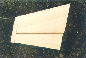
1: The all-sheet tail made from various balsa slabs is the simplest stab type that's found on countless flying model aircraft designs.
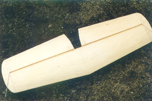
2: Some models, like the HMM 'Moonraker' for example, utilise an inset hardwood tail spar to further beef-up the basic sheet pieces.
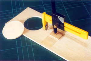
3: Get the leading/tip edges of ¼" solid sheet and framework tails contoured nicely with the ply-constructed sanding jig contained in Carl Goldberg scale kits.
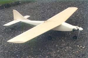
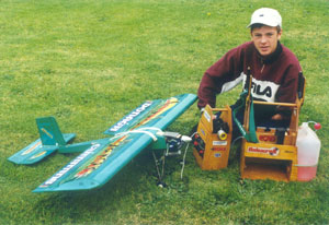
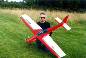
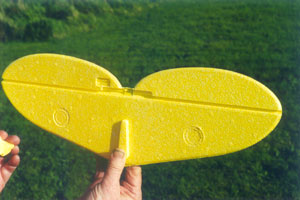
4: The ubiquitous 'Limbo Dancer' uses a built-up strip tailplane for lightness. This aspect is very important on fun-fly machines.
5: Built-up framework tail surfaces on the Multiplex 'Eldorado' features hardwood sub-spars. The completed structure is very strong when covered with Solarfilm.
6-7: Built-up sheet covered aerofoil section tails are popular on scale models, but many sport designs use 'em too.
8: Functional alloy tube tail bracing displayed to good effect on an ARTF aerobatic model.
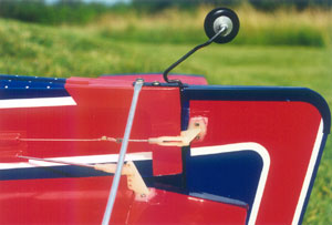
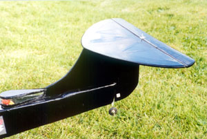
9: 'High T'! This built-up framework T-tail is featured on Francis O' Hara's OD low wing sport/aerobatic design. The horizontal stab is simply epoxied to a triangular stock-reinforced fin-top platform. The 'end-result' is very strong. Elevator snake exits through fin top rear slot.
10: Copydex contact adhesive is ideally suited to attaching wood skins to foam tail surfaces. The larger container, complete with brush applicator cap, is the size to choose for such jobs.
11-12: When repairing or hinging foam model tails, heed Feeney's advice for best results.
13: Going around in circles! The OLFA compass cutter, used with care, can produce neat lightening holes in thin-section all-sheet tail surfaces.
14-15: A sharpened tranny aerial offcut is great for punching small lightening holes in free-flight and compact R/C model tail feathers.
16: Get your ARTF model tailplane attachment routine sorted as advised in the text. When things go wrong, the results can be messy…
![]() Back to Home page
Back to Home page