
WING
WAFFLE!
Prepare for an "Uplifting" experience as
Gerard Feeney conducts his marathon mainplane masterclass...
Flying model aircraft wings can be cocked-up in many areas! The major constructional inaccuracy aspects have often been dealt with in various magazines; here are several less obvious 'Feeney Zone' wing woes (and hints) to think about - and to rectify, as suggested!
The "Hole" Truth!
Wing centre section-mounted aileron servo links sometimes clash on the fuselage-mounted radio bay servo package because either or both sets of control surface-waggling hardware have been mounted too high. Get the fuselage stuff as low as possible to begin with, but most importantly also get that aileron servo buried deeply in the wing during the initial build…
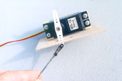
Built-up wings featuring a single central aileron servo will have a simple balsa box structure recessed into the root ribs; usually the root rib is cut away where the servo box floor/walls will fit, or the servo will fit between two ribs with 'floor' sheeting added later. Whatever method is used, ensure that your servo has adequate 'elbow-room' all round and adjust/modify box compartment dimensions accordingly. However, be very sure that the servo sinks in as deeply as possible by leaving the servo box area open on the floor surface until the lowest possible mounting position has been established. Only at this stage sheet the floor area, remembering to adjust the servo bottom spacing to clear the floor by about 1/8". In other instances, you may have to cut down through root ribs to increase the servo drop prior to mounting.
Foam/veneer wings get their single central servo holes sorted early too. Here's how I do the job…
Core Breach
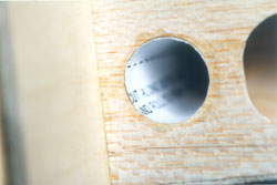
After joining the cores using 15-minute epoxy, I Biro-mark the centre section servo hole - plus an extra ¼" all round - top and bottom. Next, a sharp scalpel slices through the veneer/balsa skin, to the depth of the Number 11 blade, top and bottom. (One needs a progressive action, and a good eye, to keep the blade straight doing this!) A metal meat skewer is then passed down through the wing section at one of the servo box corners; this initial hole, once 'skewered' a couple of times, allows a Junior hacksaw blade to pass through, whereupon the servo box recess can be sawn free. I usually saw the longer chord-wise sides first, finishing with the span-wise cross-cuts; these will cut through the centre section root epoxy glue joints. A bit of finger-pushing will encourage the sawn chunk of foam/wood skin to vacate the centre section, leaving you with a gaping hole right through the wing middle!
The excavated raw foam hole sides are now skinned using 1/16" or 1/8" balsa; Sellotape or tight-fitting scrap balsa strip cross-wedges hold these epoxied or PVA'd box-side skinning panels as the glue dries. Sand the proud side sheet edges flush with the wing skin surface top and bottom after the adhesive has dried. Now, the servo mounting height is determined; hardwood beams are inserted across the open box, or recessed within the foam level with the wing skin, as applicable at this point. Some mounting beam/box side/wing skin material trimming will be inevitable to allow servo cable protrusion. The floor sheeting is now added, again remembering the floor/servo bottom gap. I usually use generous 3/8" sheet for the capping of foam wing servo boxes; this can be later planed/sanded flush with the wing outer surface easily.
Now, one has a nicely tailored aileron servo wing centre box ready to take the servo later - and, the entire servo-housing cavity has also been made good before any centre section glass bandaging takes place. Smear some five-minute epoxy into any dodgy looking servo box side/wing skin gaps if glass bandaging is on the menu.
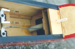
Cavities in foam wings for independent servos can be frequently too shallow. If this is the case, I cut 'em through as described and internally skin/re-fill the 'opened' top/bottom wing skin surfaces to match the deepened servo mounting depth. Independent servo boxes in built-up wings are really just inter-rib spaces with servo mounting platforms or beams added 'twixt the ribs. A novel American servo-mounting idea, used with multiple wing servos, is to screw the servo(s) to small hardwood bearers, which themselves are epoxied to the wing hatch inner surfaces. The hatches, in turn, simply screw to in-situ bay-framing hardwood beams. Highly recommended!
"Torque" About Rods!
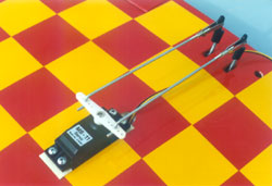
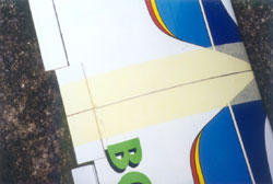
Ill-fitting torque rods can cause annoying linkage/aileron hinge-line gap problems all too easily. The key to torque rod heaven is simple: Ensure they're mounted centrally on to the false trailing edges, and make certain the actual wire torque rods themselves actually touch the false trailing edges in a smooth moving, almost gap-free manner. What this means in practice, is centreline-scribing of the balsa false trailing edge stock to establish the correct mounting symmetry and, in many cases, the slight relieving of the balsa stock to allow the torque rod bearings to recess slightly to get the wires closely fitted. The torque rod wires must lie against the false trailing edge surface - do not bury the wires themselves in the balsa; only the bearings get any recessing action!
When you've centreline-scribed the false trailing edges, establish an equidistant point either side of the wing root centre joint to place the inboard (vertical) torque rod arms. Remove a small chunk from either false trailing edge strip, to allow torque rod arm rotation, and put the torque rods in place, marking the bearing positions at the same time. Bearings are usually plastic serrated 'spikes' or flat leaves - like hinges. Whatever, either holes or slots will need making - this is why the centreline is important for alignment purposes. (If the wire torque rods need bending up by you, remember to slide on the bearings first!) Tweak the torque rods into position and have the ailerons pre-hinged so that an overall fit can be established. When the rods are nicely located, run some tiny drops of super glue into the bearing holes/slots and that's about it! (Roughen the plastic/metal bearings with sandpaper before gluing in place.) Personally, I remove the torque rod units one last time before epoxying the bearings for a slightly more gap-filling result. Be extremely careful that no glue gets on the bearing/wire rod junctions; pre-greasing with 'Vaseline' or light oil will help protect 'em further.
Now, the actual centre section trailing edge triangular stock goes on to cover the torque rods and bearings. These items need hollowing out (I use a Number 11 scalpel in concert with sharpened 1/8" brass tube) to clear the mounted fittings. They also need matching slots removed to allow torque rod arm movement in the opposite direction. Try to achieve a top/bottom edge mating line of about 1/16"; the inboard portions next the wing centre root join can be left solid. The areas where the bearings fit will most likely need more relieving to get a good snug fit. Test the pair of trailing edges and, when both fit snugly, PVA 'em in place. Use the glue sparingly and maintain a good fit with Sellotape. PVA is best for this job because, should excess glue dry on the torque rods/bearings, it'll release easily when dry if the rods are briskly rotated. Some kit trailing edge stock is of the wrong 'triangular-angle' for the overall wing aerofoil section. If this is so, either replace with correct section stock, or razor plane the false trailing edge-meeting face to the correct angle before hollowing out the pieces.
Now, with your torque rods snugly and securely bonded to the false trailing edges, subsequent aileron attachment will be that much easier. Sometimes the aileron-engaging torque rod prongs need shortening to match the aileron chord. If this is so, cut 'em before fitting the torque rods at all - use a Junior hacksaw. Filing the cut ends to a spike helps insertion.
Belting Braces!
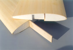
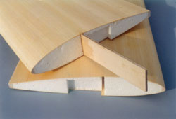
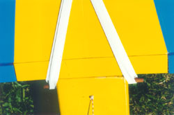
The vast majority of wings rely on ply braces to hold the halves together. On built-up wings, these braces are usually 1/16" ply and a minimum of two are used - one either side of the mainspar. More commonly, in this scenario, more braces are added - just behind the leading edge and in front of the trailing edge. The root ribs need fitting in sections to link all such inserted braces. Use SLEC plastic clamps and/or clothespegs to fasten these braces in place. Thicker 1/8", ¼" or 3/8" braces come into play on foam/veneer panels; many ARTF wings employ a fewer number of these thick braces; often they're laminated from thinner profile pieces.
Regardless of brace type, remember these basic points: Sand the ply well before joining laminated braces and/or before brace insertion. Clamp laminated braces securely; individual layers can easily slide out of alignment if not carefully checked! I personally favour impact gluing laminated ply braces together. Braces very rarely allow wing panels to slot home snugly first (or third!) try; most likely some trimming of ends/edges will be needed. A Stanley knife is useful here. In foam core /pre-assembled ARTF/built-up wing brace slots, it's best to have a very slightly sloppy brace fit - for the simple reason that it gives the glue a chance to coat all surfaces as it's forced out again during brace fitting.
When fitting braces into factory-formed root channels, pour the glue (half-hour epoxy only!) first into the wing root slot. I load the epoxy onto a plastic or thin ply spatula, then I 'dump' the glue carefully into the slot with the wing panel held vertically root-up. A long 1" strip of 1/32" ply is ultra-useful for coating narrow slot interior faces! Now, insert the brace. Removing/inserting the brace will allow the adhesive to really coat all mating surfaces effectively. If braces show dry patches, re-coat 'em and/or the slot interior. Letting the lovingly inserted brace(s) dry thoroughly, before feeding on the matching panel, is best to ensure unruffled panel pairing later.
Some root slots in foam wings feature factory-removed upper/lower sheeting. If this is so, the braces may be mildly oversize; in which case they're planed/sanded after panel joining. Alternatively, balsa brace capping strips are added and sanded flush with the wing skin later. Often, ply braces lie just below the wing skin when inserted. No real problem here - just ensure straight brace insertion, or they can burst through the wing skin suddenly!
"Tape" Recording
Stop oozing adhesive from spoiling joined wing root areas by wrapping the adjacent root rib wing skin edges with paper masking tape before attempting the joining ritual. This way, when brought together, any squeezed-out glue will land on the masking tape protection strips rather than the wood/ARTF film surface. Now, one isn't overly bothered about wiping away the over-run, so more time can be devoted to wing half-joining alignment. The excess glue can then be wiped off - or, it will come away when the tape is peeled free after curing has finished. Simple but effective!
Hard Points...
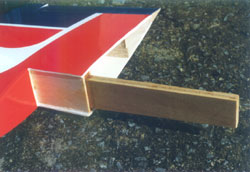
Thin ply plates added to wing centre section trailing edges are almost mandatory in the ongoing struggle against wing-retaining rubber band/bolt 'clamping' tension! If your model being built doesn't feature a 'plated' wing trailing edge, modify it now! They're so easy to make and the benefits are tremendous.
Cut a rectangle out of 1/16" ply; make the rectangle from a 1" wide strip cut about ½" over-wide span-wise relative to the attached bands or passed-through bolts. The plate can also be made from thicker ply - say, 1/8" or even ¼" (suitable for recessing into wing skins) depending on the model size and type. Gently score the plate chord-wise on the wing-facing surface to assist dihedral-bending (if dihedral is present), then glue it in place. Personally, I contact glue 'em, as it's neater. If adding plates to pre-covered wings, remove the covering 1/16"inside the ply plate outline, so that the glued plate will neatly cover the film edges without bare wood showing. Film-cover/dope/paint the ply plate before attaching.
Hot Rods!
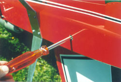
Drilling the leading edge wing dowel hole, for single centrally-inserted dowel rods, on either built-up or foam wings, is a pain in one's tungsten-tipped bit! Why so? Well, the root section glue bond efficiently deflects drilling efforts, so you just screw about off-centre in an ineffective manner! The remedy is simple: Use a short length of old sharpened tranny aerial, the same diameter as the wing dowel used, to bore from the leading edge in through the central rib joint adhesive mass. This action removes a 'plug' which can be fished out with a scalpel blade or tweezers. Now, after a bit of filing to clean up the hole, the dowel can be inserted without hassle. Removing the dowel 'tunnel' from foam core roots, before joining the wing halves, is another way of easing dowel insertion - use the sharpened aerial and/or a round file for this task.
True Grit
Black waterproof abrasive paper makes excellent wing 'walkway' simulation material on semi-scale or 'proper' scale flying models. Just choose the paper grit-grade which best suits your model's size, then cut the walkway pattern out using a very sharp Number 11 scalpel or terribly keen Stanley blade. The abrasive paper grit offers some resistance, so slice the paper over a cutting mat and press the blade well in whilst being guided by a straight edge - a steel rule is ideal. The finished walkway areas are glued to tissue/dope or film-covered airframes with impact adhesive (sand the model surface first); cyano can also be used, but the overall surface contact may be patchy.
Taking The Tube!
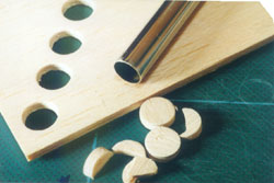
Rolled paper tubes, passing through wing rib holes, is an old method to route aileron/flap servo extension leads. The American 'Top Flite' scale kits utilise this practice frequently to good effect; their 'Bonanza' even has the tube patterns printed on the plan ready to be cut out, rolled up, and poked through the ribs! You may not have to actually glue the rolled tube shut along its length - the rib holes maintain the paper 'tunnel' shape very well. However, one does need to anchor the tube to each rib hole 'pass-through' point to discourage possible lateral slippage. Cyano or Deluxe Materials' 'R/C Modeller's Glue' is good for this paper/balsa anchorage task. You can use this paper tube cable-conduit trick on any built-up wing if needed - stout drawing paper is ideal for the job.
Talking
of routing leads in wings, many people hot-wire cut channels in foam wings
and this is excellent if done carefully. I sometimes hollow out the foam
into a narrow groove just behind the leading edge strip, insert the cables
through pre-cut lead-ins/lead-out channels, then glue the leading edge
strip on with PVA. It's a tad permanent but, if done carefully, the system
works well. Of course, one caps all such servo cable lead channels in
wood-skinned foam wings with balsa strip, which is subsequently sanded
to match the overall wing section. Even non-skinned foam wings will need
such balsa strips added to cover cable channels;
soft-ish
balsa ensures easy sanding.
Swinging Doors!
Spindly
wing-mounted piano wire undercarriage legs never look overly brilliant on
any R/C model, but they look absolutely terrible dangling beneath sport/semi-scale
designs! Get over this problem by cutting dummy wheel-well doors from good
quality 1/16" ply, so that your pride and joy looks absolutely fabulous
for those static photo shoots - or even during flying sessions from smooth
grass and/or tarmac/concrete surfaces.
I just 'guesstimate' the door shapes (using a drawing or picture of the full-size
aircraft as a rough guide) onto graph paper, sketching the 'that looks about
right' outlines on with a pencil. Curved areas are marked with suitable diameter
tin cans, plates, saucers, coins and/or French curves; the graph paper grid
pattern takes care of the straight lines. The door shapes are transferred
to the ply by cutting 'em out and 'Pritt-Sticking' the paper patterns directly
to the wood. The stuck-on door templates can now be outlined with a Biro or
pencil, leaving a 'pre-printed' ply surface to cut around once the paper templates
have been removed. One can also place carbon paper 'twixt graph-paper patterns
and wood, and trace the door shapes onto the wood. The doors are cut out using
a sharp Stanley knife and/or fret saw; then they're cleaned up using 400-800-grit
glass-paper.
The doors simply plug into the lower wing surface, immediately beside the
legs, using two short lengths of cocktail stick cyanoed to each door 'top'
(wing-meeting) wheel-facing edge. The cocktail sticks engage in matching 1/16"
holes drilled in through the wing skin/hardwood undercarriage mounting blocks;
these pegs can be lightly glued or (preferably) just left a tight push-fit.
Small saddle clamps, or custom-made thin alloy strips, secured to the ply
with cut-down 6BA bolts, may be placed over the vertical leg wires near the
axle bends for greater door stability if so desired. However, in practice,
this feature usually ain't necessary.
Many sport-scale 'Feeney Fliers' have been thus treated and, whilst I won't
pretend the idea is highly durable, it sure has made a huge difference to
the finished models' appearances. Why not try it for yourself right now?
End of The Line
Control surfaces on wings (and aerofoil-section tails) can be shaped to section better if 'root/tip' templates 'show the way to go' at either end. Many plans feature these section templates and it's worth cutting 'em out and pasting 'em in place whilst the 'sectioning' action is carried out. The Top Flite Bonanza makes good use of these items, and their inclusion is welcome to get the complex flap leading edge curvature sorted. A minority of plans may also include 'concave' wing and aileron/flap leading edge template patterns. Basically, these shapes are transferred to 1/16" ply or stout card and cut out; they're a snug fit around/over the leading edges only when you've carved/sanded the airframe items to the correct sectional profile.
Hole- Hearted!
Anchor
bolt-holes going through wing structures can be beefed-up internally by the
inclusion of suitable internal-diameter plastic tubes - usually sourced from
one's scrap box! When lightly epoxied within the trailing edge bolt pass-through
holes, such plastic tubes will protect delicate polystyrene foam or even balsa
wing 'stuffing' - and, the bolts are nicely stabilised too during the 'screwing'
procedure! It's a good idea to leave these 'lining-tubes' fractionally proud
relative to the wing top/bottom surfaces, then sand 'em flush during the airframe
finishing stage. The shoulder-wing Multiplex 'Eldorado' sportster uses a single
trailing edge captive bolt which is tightened from beneath the fuselage through
a hard plastic tube which extends vertically upwards through the rear radio
bay. The Top Flite Bonanza uses hard cardboard tube wing bolt hole liners
- included in the kit, naturally! And, before you ask, loo roll cardboard
tube is too large - unless you're building a full-size machine with bolt-on
wings!
While I'm on about bolt-holes through wings, a hot 6" steel nail is ideal
for clearing the bolt-holes (or wing dowel holes in fuselages) of film covering.
Heat the nail in a gas flame (hold the nail with a damp cloth!) until it's
dull red, then remove and allow it to cool for a few seconds. The temperature
should now be sufficient to burn through the filmed hole openings without
melting any plastic tubes installed. You may need to repeat the nail 'heating
and plunging' exercise for multiple hole clearing.
The Hook and I...
Threading sailplane wing root 'cross-fuselage' rubber bands in through the fuselage side holes, from one wing root rib anchor hook to the other (to establish wing retention span-wise tension), is a true bitch of a job if one has the typical 'bulky fingers/slender fuselage' scenario to contend with. The answer is simple - just bend up a wire 'shepherd's crook'-type device so that one may grab, pull and slip those damned rubber bands into position. The Cambrian 'Elan' sailplane kit (which I reviewed in 'RCM&E' way back in 1993!) provided just such a hook, pre-bent to shape, which I've held on to carefully ever since! It has proved to be a Valium-saver on many occasions, I can tell you! Bend one up from 16SWG wire now, and save yerself some grief!
Wing ARFS
Those
pesky ARTF models that we all know and love (!) can throw up many irritating
airframe problems - and their wings can be quite lacking in places…
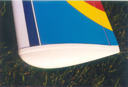
Factory-fitted moulded plastic wing tips are sometimes a less-than-perfect
fit over the wing structure. One has often winced at pronounced glue-less
gaps spoiling that 'perfect finish' as plastic tip shells only make partial
contact with the (unsanded!) covering film beneath. The remedy is ultra-simple
of course - just run some adhesive into the gaps using a pointy stick to cram
the glue well in under the plastic; then, the 'Mk. One Fingertip' cleans excess
adhesive away before it dries. 15-minute epoxy is best, but any of the 'specialist'
adhesives, like Deluxe Materials' 'Fusion' or ' Super Crylic!', are ideal
too. Check first on scrap material that the glue won't react with the ARTF
covering film finish. If you can slip a small piece of 400-grit glass-paper
in 'twixt plastic tip edge and model structure before gluing, a better 'key'
will be created; but this action ain't really necessary in most cases.
ARTF model
wing/control surface pre-glued hinges can be very suspect when the 'pull-test'
is forcefully applied! If yer hinges pull out, re-sand leaf types to improve
the glue key and re-install 'em with 15-minute epoxy. I always cyano the hinges
into control surfaces first using thick slow-acting super glue. Then, when
these are firmly held, I epoxy 'em into the wing halves. If the hinges are
of the miniature 'door' variety, some Vaseline or light oil must be carefully
applied over the pivots before gluing-up to prevent 'seizures' during installation!
'Barb' hinges go into drilled holes, so 15-minute epoxy on all surfaces is
best here to fill any 'tweaking' gaps present. I also grease barb hinge pivots
before gluing, and I attach 'em to the control surfaces first; this allows
a more leisurely and accurate fitting session.
Being a 'belt-and-braces' aeromodeller, I frequently pin the aileron and flap
(and elevator/rudder!) hinges at the root and tip areas. Cocktail stick pegs,
going into 1/16" holes drilled right through the flying and control surfaces
after hinging is completed, anchors the already (hopefully!) well-glued hinges
further. A drop of cyano or Deluxe Materials' 'Super 'Phatic!' sticks the
pegs after they've been cut flush above and below the wing with a single-edge
razor blade. Scraps of Solarfilm, Solartrim, or ARTF film covering offcuts,
hides the pegging holes.
Feature Film
Puncture-wounds
and tears in open structure ARTF aircraft wings are a true pain in the
sticky-back plastic to fix! It is possible though to seal clean instant
aeroplane covering with Solarfilm and/or Solartrim (after a fashion) as
follows.
When repairing with Solarfilm, cut the ragged ARTF film edges away with
a sharp scalpel and de-grease the area with meths. (Be careful not to
rub too hard or you'll remove the surface pigmentation!) If it doesn't
dissolve the pre-printed decoration, some 'Clearcoat' may also be dabbed
on very sparingly (after de-greasing) with a fingertip or small wad of
tissue where the film is to be stuck in place (after gently abrading the
areas first). Cut out a piece of Solarfilm to cover the damage with about
a ½" overlap all round. Now, with a modelling iron, gently
tack the film at its central and corner points to establish some skin
tension once more; then seal it all around as per normal filming practice.
Crank up the iron to a slightly higher heat and shrink the repair all
over; be careful not to nick/deface the original ARTF surrounding film
in the process! Strips of matching Solartrim can be applied over the shrunk
film patch edges for added security; brushed-on (new) clear polyurethane
varnish helps further seal the repair against air/oil ingress.
Solartrim alone can also hide ARTF film damage - in fact, I've sealed
entire inter-rib bays with it! Again, it won't adhere to a greasy under-layer,
so wipe those prepared 'wound' edges with meths once more! The same over-size
patch-cutting approach is followed as with the film; then it's aligned
over the tear/rip/gaping hole with only about half its backing sheet peeled
away to prevent premature inaccurate sticking. Gently finger-dab the Solartrim
centrally at one edge then, maintaining tension along the repair's longest
axis, peel the entire backing sheet away. Stick it centrally at the opposite
end, then gently dab it down centrally at
right-angles to the first tacking points. Next, gently but firmly, dab
the entire repair patch edges down, being careful to avoid excess sagging
in the process! (Yup, one needs medication during this carry-on!) Solartrim
will wilt over large holes, so try to get it as taut as possible during
the initial sticking stage! Now, waft a heat gun manfully over the patch
and those remaining sags will disappear leaving you with a beautifully
sealed skin once more.
The entire wing area where the repair has been made will probably need re-shrinking with the heat gun all over, whether using Solarfilm or Solartrim patches. Clear varnish patch edge-sealing may follow if so desired. With either patching material, some strips of ordinary clear Sellotape, stuck over the clean patch edges before varnishing, also help seal the damaged areas. Or, the tape strips can be applied over the dried varnish if preferred.
Flying Colours
The big
problem with Solarfilm/Solartrim repairs over instant aircraft wings (and
the entire airframe!) is the profound lack of colour co-ordination. It's
unrealistic to expect that European/American heat-shrink films will colour-match
the Far Eastern factory-applied stuff, so I'm afraid you just gotta live
with the aesthetic consequences! I've said this before, but I must repeat
myself: When the hell will you ARTF aircraft manufacturers produce large
colour-matched trim/covering sheets to suit all the major ARTF aircraft
designs out there??? It's a bit much to expect modellers to cobble about
with partially incompatible covering
materials - both 'bonding' and colour-wise - when your oh-so-easily damaged
creations get busted so often!!! Get a move on, and help the World's frustrated
ARTF'ers - now!!!
And, on that note, I'll 'wing it' for now. Happy aeromodelling!
Picture Captions:
 |
 |
|
An independant wing half aileron servo mounted to
small hardwood beams which themselves are stuck to the hatch interior surface. A great servo mounting idea. |
Follow
Feeney's 'torque rod talk' given here and
achieve neat results like this |
 |
 |
|
Brace
yourself! Fit those wing joing ply braces as
advised and you'll be flicking happily, secure in the knowledge your model will not fall asunder! |
As
in 3.
|
 |
 |
|
As
in 3
|
Masking
Tape being used to protect the root area of |
 |
 |
|
A
simple ply trailing edge stripprovides oodles of anti
crush protection when those ruibber bands (or bolts) get up tight! |
A
sharpened tranny aerial offcut is ideal for cutting
central leading edge wing dowel holes in through glue joints, it's also great for cutting thin balsa as shown here |
 |
 |
|
The
'Hole Story' Up close and personal in Gerard's Top Flite |
The
Multiplex 'Eldorado' sportster uses an interesting 'in fuselage'
tube conduit to guide the single trailing edge wing retaining bolt.
Similar plastic or cardboard tubes can be inserted into wings to
guide bolt insertion.
|
 |
 |
|
As
in 10
|
As
in 10
|
 |
 |
|
Are
the wing tips of your ARTF model securely fastened?
No? Follow Feeney's 'wing tips' to solve the problem |
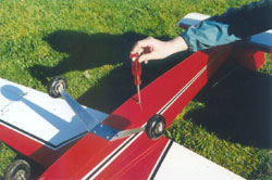
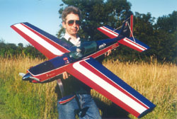
Get
your ARTF aircraft covering repairs sorted as
advised here. Gerard hates ARTF models, and so he had to be persuaded to hold on to this (great flying) 'Extra 300' whilst the picture was taken. |