Binary clock project

This binary clock is based on the PIC16F628A from microchip and drives 20 LED’s to tell the time in 24 hour format.
How to read a binary clock
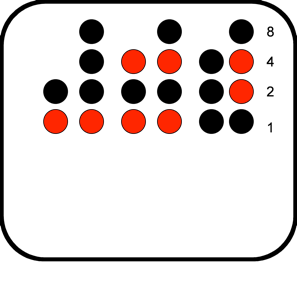
In a BCD binary clock the LED’s are arranged in 3 columns to represent hours, minutes and seconds. Within each of these columns are two further columns representing 10’s
single digits. The time is then told by adding up the lit LED’s in each column according to
number on the rows.
So in this example and picture above the
time is 11:55:06
How it works
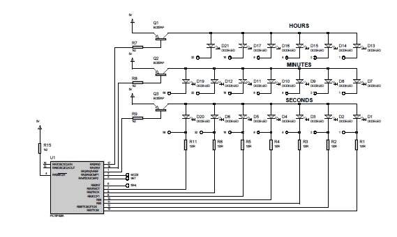
Schematics and layouts for this project can be downloaded here in a pdf format .Using a PIC16F628A this binary clock project uses the mains frequency as an interrupt and counts these pulses to display the time in binary coded decimal. In the schematic below you can see that the pic drives the display in a multiplexed fashion for hours minutes and seconds, cycling around this display fast enough ensures that the display does not flicker
The multiplex routine runs of the pic’s internal 4MHz clock ensuring the refresh frequency is not visible. The binary clock gets its time base signal from the mains itself as shown below in the power supply schematic. The basic power supply is a standard full bridge rectified power supply feeding into a 7805 linear regulator to supply the 5V to the pic . The input to the clock is a 12V AC supply with a frequency of 50Hz.
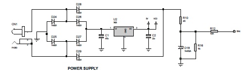
In parallel with the full bridge are diodes D28 & D29 which have effect of feeding the input of R10 with a fully rectified AC signal up to 12V, this signal is then fed via R10 into the zener D18 which clips the signal at a maximum of 4.7V leaving a 100Hz signal to be fed into the interrupt of pic. The reason for R16 is to ensure that the capacitance of the zener gets fully pulled down to ground every half cycle.
Building the Clock
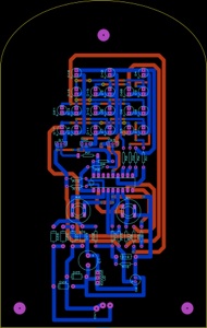
In order to build the clock you will need to make a double sided PCB the artwork is available in the schematics pdf file here. Alternatively you may want to order a board I have used PCBPool successfully in past.
If you do this you will need to send them the layout file here it is a Labcenter Proteus file.
When you have a PCB you will also need the components listed in the components box below
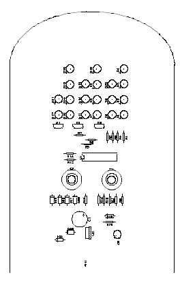
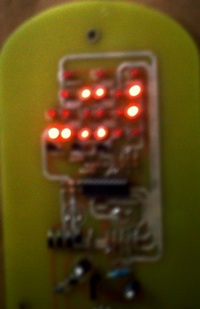
The components need to be inserted according to
the silkscreen above, when the build is complete
the PIC needs to be programmed, the assembly file
is available here

COMPONENTS LIST
Binary Clock
Resistors
Quantity Component Value
7 R1-R6,R11 120R
6 R7-R9,R13-R15 1k2
1 R10 470R
1 R12 100K
1 R16 10k
Capacitors
1 C1 470uF
1 C2 22uF
Semiconductors
1 U1 PIC16F628A
1 U2 7805
Transistors
3 Q1-Q3 BC557AP
Diodes
20 D1-D17,D19-D21 DIODE-LED
1 D18 1N4732A
6 D24-D29 1N4001
Miscellaneous
2 B1,B2 BUTTON
1 CN1 Socket