GPIO for the Raspberry Pi
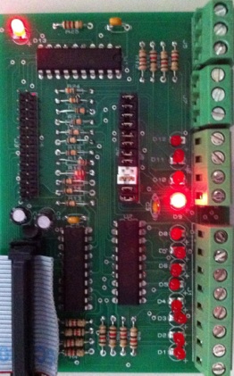

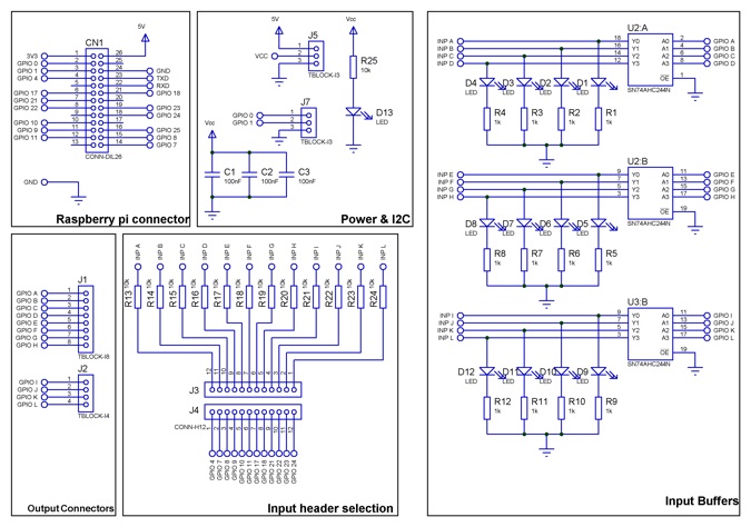
This is a basic GPIO board for the raspberry pi that brings out 12 GPIO lines(At 3.3V I/O) the I2C and
power ports via a set of input and output buffers to terminal blocks to allow for easier wiring to external circuits. It also consists of 12 LED’s that indicate the state of the logic signal.
Schematic 1:- Input buffers, Power, Input selection and terminal blocks
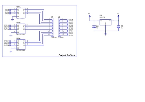
Schematic 2 :- Output buffers and LDO
The 12 input/output connector terminal blocks are connected to GPIO A-K and output selection is chosen with jumpers between J6 & J8. Input selection is chosen by placing jumpers between J3 & J4, Try to ensure that each of the GPIO terminal A-K is selected as either an input or an output.
All terminal connections connect back through U2 A&B and U3B to the LED indicators that indicate the
logic levels at terminal blocks.If connected as an input then this signal is also routed back to Raspberry pi GPIO connector via a 10K resistor. This ensures that if connected to an output by mistake then there is
no shorted connection.
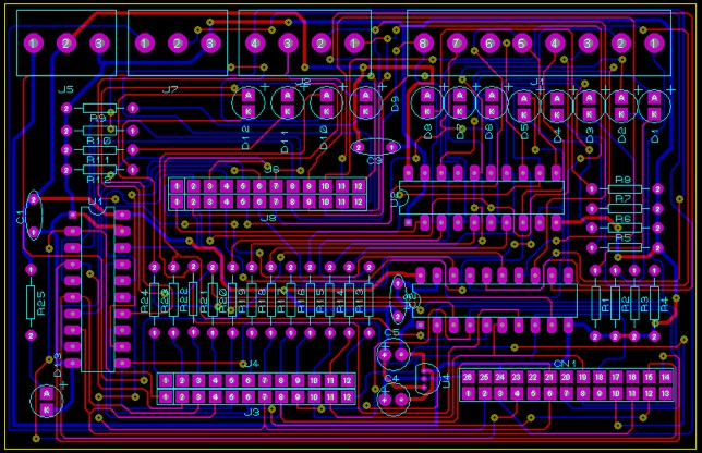
The PCB is a 2 layer board designed for through hole components, power present is indicated by D13.
The bill of materials for this project is
Bill Of Materials
=================
QTY PART-REFS VALUE
--- --------- -----
Resistors
---------
12 R1-R12 1k
13 R13-R25 10k
Capacitors
----------
3 C1-C3 100nF
2 C4,C5 10u
Integrated Circuits
-------------------
3 U1-U3 SN74AHC244N
1 U4 MCP1702
Diodes
------
13 D1-D13 LED
Miscellaneous
-------------
1 CN1 CONN-DIL26
1 J1 TBLOCK-I8
1 J2 TBLOCK-I4
4 J3,J4,J6,J8 CONN-H12
2 J5,J7 TBLOCK-I3
Connecting up to WiringPi
In order to test the board I’m using the excellent WiringPi from Gordons Projects go to his website and follow the download instructions for installing WiringPi. The table below shows how wiringPi Maps to the GPIO
Board.
Writing a small script below or download here
#!/bin/bash
for i in 0 1 2 3 4 5 6 7 8 9 10 11 12 13 14 15 16; do gpio mode $i out; done
while true
do
for i in 0 1 2 3 4 5 6 7 8 9 10 11 12 13 14 15 16; do gpio write $i 0; done
sleep 1;
gpio write 5 1
sleep 1;
gpio write 4 1
sleep 1;
gpio write 3 1
sleep 1;
gpio write 2 1
sleep 1;
gpio write 1 1
sleep 1;
gpio write 0 1
sleep 1;
gpio write 14 1
sleep 1;
gpio write 12 1
sleep 1;
gpio write 13 1
sleep 1;
gpio write 10 1
sleep 1;
gpio write 11 1
sleep 1;
gpio write 7 1
sleep 1;
done
Lets the GPIO board switch on each output in turn as in the video below
Controlling from Python
Now the board is functional we can try and control it from python, this is my first python program so be
kind.. so this is a small LED chaser program it switches each LED on in order for 1 second and then
moves onto the next one when it reaches the end it does the reverse and continues in an infinite loop.
First I installed Geany as an Editor type
apt-get install geany
Next make sure it builds using sudo as explained here
Run geany from the start menu under programming languages and either download LED Chase.py
or type in the code below not elegant I know but it does the job.
#!/usr/bin/env python
import RPi.GPIO as GPIO
from time import time, sleep
GPIO.cleanup()
GPIO.setwarnings(False)
GPIO.setmode(GPIO.BOARD)
GPIO.setup(18, GPIO.OUT)
GPIO.setup(16, GPIO.OUT)
GPIO.setup(15, GPIO.OUT)
GPIO.setup(13, GPIO.OUT)
GPIO.setup(12, GPIO.OUT)
GPIO.setup(11, GPIO.OUT)
GPIO.setup(23, GPIO.OUT)
GPIO.setup(19, GPIO.OUT)
GPIO.setup(21, GPIO.OUT)
GPIO.setup(24, GPIO.OUT)
GPIO.setup(26, GPIO.OUT)
GPIO.setup(7, GPIO.OUT)
while 1:
GPIO.output(18, True)
sleep(1)
GPIO.output(18, False)
GPIO.output(16, True)
sleep(1)
GPIO.output(16, False)
GPIO.output(15, True)
sleep(1)
GPIO.output(15, False)
GPIO.output(13, True)
sleep(1)
GPIO.output(13, False)
GPIO.output(12, True)
sleep(1)
GPIO.output(12, False)
GPIO.output(11, True)
sleep(1)
GPIO.output(11, False)
GPIO.output(23, True)
sleep(1)
GPIO.output(23, False)
GPIO.output(19, True)
sleep(1)
GPIO.output(19, False)
GPIO.output(21, True)
sleep(1)
GPIO.output(21, False)
GPIO.output(24, True)
sleep(1)
GPIO.output(24, False)
GPIO.output(26, True)
sleep(1)
GPIO.output(26, False)
GPIO.output(7, True)
sleep(1)
GPIO.output(7, False)
GPIO.output(26, True)
sleep(1)
GPIO.output(26, False)
GPIO.output(24, True)
sleep(1)
GPIO.output(24, False)
GPIO.output(21, True)
sleep(1)
GPIO.output(21, False)
GPIO.output(19, True)
sleep(1)
GPIO.output(19, False)
GPIO.output(23, True)
sleep(1)
GPIO.output(23, False)
GPIO.output(11, True)
sleep(1)
GPIO.output(11, False)
GPIO.output(12, True)
sleep(1)
GPIO.output(12, False)
GPIO.output(13, True)
sleep(1)
GPIO.output(13, False)
GPIO.output(15, True)
sleep(1)
GPIO.output(15, False)
GPIO.output(16, True)
sleep(1)
GPIO.output(16, False)
GPIO.output(18, True)
sleep(1)
GPIO.output(18, False)
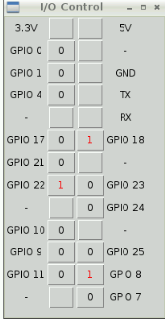
Controlling the GPIO Port from a GUI
Taking this one step further and combining Tkinter and GPIO lets
us control the outputs from a GUI. You can click on the buttons to toggle
the GPIO outputs on or off represented by a 0 or a 1. The python code
can be downloaded here.
GPIO board for the Raspberry Pi :- Complete
