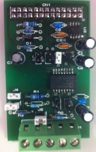
Buy PCB
27 Available
€7.99
Buy PCB
27 Available
€7.99

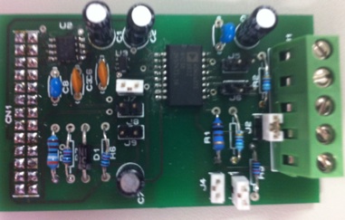
Buy assembled board
1 Available
€34.99
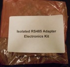
Buy Kit
1 Available
€25.99
Isolated RS485/422 converter for the raspberry pi

Download build manual Isolated RS485 Adapter Build Manual.pdf
This Isolated RS422/485 converter connects to the Uart 0 port on the GPIO connector of the raspberry pi. As this is only a mini Uart on pi providing TX and RX only it provides a challenge for the direction control on in the RS485 mode. In this schematic this is achieved using a 555 timer(A trick borrowed from RE Smith and Jan Axelson).
Schematic:- Isolated RS485/422 converter
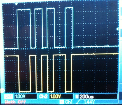
The 555 timer U2 (Make sure to use a CMOS one that works to <3.3V) works as a monostable set for around 40 us(Via R3 & C3), every time the TXD pin goes low it resets the timer via D1 and when it goes high the monostable triggers, after the monostable period it disables the transmitter but the lines A&B are still pulled apart (Representing a 1) by R2 & R4.
In this way the transmitter is automatically disabled within 40us of the last low to high transition on the TXD pin. The operation can be seen in the scope plot below the blue plot is the DE input and the yellow trace is the TX input, shortly after the last low to high transition the DE input disables the transmitter.
The board is isolated by using the ADM2687E Isolated transceiver, this chip does most of the hard work providing isolated signal and power supplies from the 3.3V input supply, because the operating current of the ADM2687E is higher than the 50mA limit of the raspberry pi it is supplied from another linear regulator the ADP122 that supplies enough current from the 5V supply to the 3.3V input of the ADM2687E.
If automatic enable isn’t needed(RS485 DE) then Jumper J7 can be removed and J9 inserted then GPIO 17 can be used to drvie the DE/RE pin
To select the different modes of operation below is a table showing which jumpers should be fitted,
The board is a 2 layer board the diagram below shows the placement of the jumper connections note there should never be any connections that bridge the isolation gap between both sides of U1 as this is the isolation barrier providing up to 5kV isolation. RS485/422 cables should use shielded twisted pair, the shield should be connected at one end of the cable to ground if connected on this adapter connect to pin 5. Note don’t connect to both ends as it can form a ground loop.
The bill of materials for this project is listed below
QTY PART-REFS VALUE
--- --------- -----
Resistors
---------
1 R1 100
2 R2,R4 560
1 R3 3.9k
1 R5 120
2 R6,R7 10k
Capacitors
----------
4 C1,C2,C4,C7 10u
2 C3,C6 10n
2 C5,C8 100n
Integrated Circuits
-------------------
1 U1 ADM2687E
1 U2 555 (Make sure to use a low voltage one like TLC555)
1 U3 ADP122
Diodes
------
1 D1 1N4148
Miscellaneous
-------------
1 CN1 CONN-DIL26
1 J1 TBLOCK-I5
8 J2-J9 CONN-H2
Isolated RS422/485 converter :- Complete