LED Thermometer
Building the display board
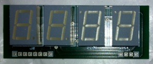
The display consists of 4 seven segment SA56
displays from kingbright, they are available in various
LED colours in this case we are using Red.
This enable’s the display to be viewed clearly through
the red filter on the Evatron enclosure.
The display is a multiplexed common anode display, the seven segment displays are mounted with the first 2
digits the correct way up and the second two digits
reversed so we can form the degree C character,
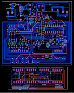
Building the base board
The base board is designed so it can be used either as an LED clock or thermometer board, in this project as a thermometer board.
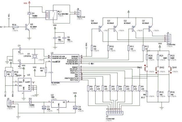
In the schematic below the PIC16F628A multiplexes the display driving the Anodes via the PNP transistors and displays the seven segment digit code on port B.
Power is supplied via the 7805, and the temperature is read from the LM75 over I2C, SDA is multiplexed to be used alternately to drive the display and read the temperature from the temperature sensor.
Bill Of Materials
=================
QTY PART-REFS VALUE
--- --------- -----
Resistors
---------
8 R1-R8 47R
4 R9-R12 1K2
6 R13,R15-R19 10K
1 R14 1K
3 R20-R22 `` 820R
Capacitors
----------
2 C1,C2 47p
2 C3,C4 470u
2 C5,C6 100n
Integrated Circuits
-------------------
1 U1 PIC16F628A
1 U2 7805
1 U3 LM75
Transistors
-----------
4 Q1-Q4 BC559AP
1 Q5 BC108BP
Diodes
------
2 D1,D2 1N4004
Miscellaneous
-------------
1 J1 CONN-SIL4
1 J2 CONN-SIL8
2 J3,J4 TBLOCK-I2
1 J5 CONN-SIL2
1 RL1 PCJ-105D3MH
3 SW1-SW3
1 X1 CRYSTAL
Software
The software is wirtten in Hitech C and can be downloaded here or seen below
#include <htc.h>
#include <pic16f628a.h>
#include <stdint.h>
#define SCL TRISA4 // I2C bus
#define SDA TRISA0 //
#define SCL_IN PORTA,RA4 //
#define SDA_IN PORTA,RA0 //
#define TMR0_2 (TMR0 & 1<<2)
#define LM75AD 0b10010000
__CONFIG (0x3D11);
unsigned char mpx_cnt;
unsigned char tempmsb;
unsigned char templsb;
unsigned char tempBCD1;
unsigned char tempBCD2;
const int pat7seg2[10]=
{
0b10000001,//0
0b11011101,//1
0b01000011,//2
0b01010001,//3
0b00011101,//4
0b10110000,//5
0b00100001,//6
0b11010101,//7
0b00000001,//8
0b00010001,//9
};
const int pat7seg3[10]=
{
0b00000001,//0
0b00101111,//1
0b01000010,//2
0b00100010,//3
0b00101100,//4
0b00110000,//5
0b00010000,//6
0b00101011,//7
0b00000000,//8
0b00100000,//9
};
const int pat7seg4[10]=
{
0b10000001,//0
0b10101111,//1
0b11000010,//2
0b10100010,//3
0b10101100,//4
0b10110000,//5
0b10010000,//6
0b10101011,//7
0b10000000,//8
0b10100000,//9
};
void Wait()
{
unsigned char i;
for(i=0;i<100;i++)
_delay(10000);
}
void i2c_dly(void)
{
_delay(20);
}
void i2c_start(void)
{
SDA = 1; // i2c start bit sequence
i2c_dly();
SCL = 1;
i2c_dly();
SDA = 0;
i2c_dly();
SCL = 0;
i2c_dly();
}
void i2c_stop(void)
{
SDA = 0; // i2c stop bit sequence
i2c_dly();
SCL = 1;
i2c_dly();
SDA = 1;
i2c_dly();
}
unsigned char i2c_rx(char ack)
{
unsigned char x, d=0;
SDA = 1;
for(x=0; x<8; x++) {
d <<= 1;
do {
SCL = 1;
}
while(SCL_IN==0); // wait for any SCL clock stretching
i2c_dly();
if(SDA_IN) d |= 1;
SCL = 0;
}
if(ack) SDA = 0;
else SDA = 1;
SCL = 1;
i2c_dly(); // send (N)ACK bit
SCL = 0;
SDA = 1;
return (d) ;
}
bit i2c_tx(unsigned char d)
{
char x;
static bit b;
for(x=8; x; x--) {
if(d&0x80) SDA = 1;
else SDA = 0;
SCL = 1;
i2c_dly();
d <<= 1;
SCL = 0;
i2c_dly();
}
SDA = 1;
i2c_dly();
SCL = 1;
i2c_dly();
b = SDA_IN; // possible ACK bit
SCL = 0;
return b;
}
void ReadI2C()
{
SDA = SCL = 1;
SCL_IN = SDA_IN = 0;
i2c_start(); // send start sequence
i2c_tx(0xE0); // SRF08 I2C address with R/W bit clear
i2c_tx(0x00); // SRF08 command register address
i2c_tx(0x51); // command to start ranging in cm
i2c_stop(); // send stop sequence
}
void main()
{
OPTION_REG = 0b11010111;
//Initialize PORTD
//PD0 as Output
CMCON=0B00000111;
TRISA=0B11111111;
PORTB=0b11111111;
PORTA=0b11100000;
tempmsb=0;
templsb=0;
while(1)
{
TRISA=0B11111111;
PORTB=0b11111111;
PORTA=0b11100000;
i2c_dly;
//Set Pointer to the Temperature Register
i2c_start();
i2c_tx(0b10010000);
i2c_tx(0b00000000);
//Eead temperature sensor
i2c_start();
i2c_tx(0b10010001);
tempmsb=i2c_rx(1);
templsb=i2c_rx(0);
i2c_stop();
tempmsb=tempmsb-6;
tempBCD1=tempmsb/10;
tempBCD2=tempmsb % 10;
TRISA=0B11111111;
TRISB=0B11111111;
for(mpx_cnt=0;mpx_cnt < 1000000/2048/4; mpx_cnt++)
{
TRISA=0B11111111;
TRISB=0B00000000;
while(!TMR0_2)
;
PORTB=pat7seg4[tempBCD1];
TRISA=0B11110111;
PORTA=0B11110111;
while(TMR0_2)
;
while(!TMR0_2)
;
TRISA=0B11111111;
PORTB=pat7seg3[tempBCD2];
TRISA=0B11111011;
PORTA=0B11111011;
while(TMR0_2)
;
while(!TMR0_2)
;
TRISA=0B11111111;
if((templsb & 0B10000000))
{
PORTB=pat7seg2[5];
}
else
{
PORTB=pat7seg2[0] ;
}
TRISA=0B11111101;
PORTA=0B11111101;
while(TMR0_2)
;
while(!TMR0_2)
;
TRISA=0B11111111;
PORTB=0B00100011;
TRISA=0B11111110;
PORTA=0B11111110;
while(TMR0_2)
;
}
}
}
Seven segment LED ambient temperature meter using the PIC16F628A and LM75