|

|
Diffraction of light.
(Thomas O’Sullivan 1997)
Diffraction:
The spreading or bending of waves when they pass through an aperture or round the edge of an object.
If light is made pass through slits that have a width of the same magnitude as the wavelength of the light, then just as in the case of any wave, constructive and destructive interference occurs.
Constructive interference occurs when two crests meet, while destructive interference occurs when a crest and a trough meet.
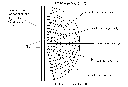
In the diagram below we see the constructive interference which occurs when two coherent sources (the slits) emit waves that are in phase with one another.
This interference results in a series of bright fringes, which could be viewed with a spectrometer (See To Measure the Wavelength of monochromatic light) or on a screen.
On a screen the diffraction gives bands or fringes of brightness and darkness. The physicists Thomas Young (See Biographies of modern physicists) first demonstrated this.

Light from a source arrives at two slits, which is constructed by painting a piece of glass black and then etching two lines on it. The two slits then act as sources of coherent waves. These waves spread out from the slits and constructive and destructive interference occurs. A suitably placed screen will show this effect as a sequence of bright and dark fringes.
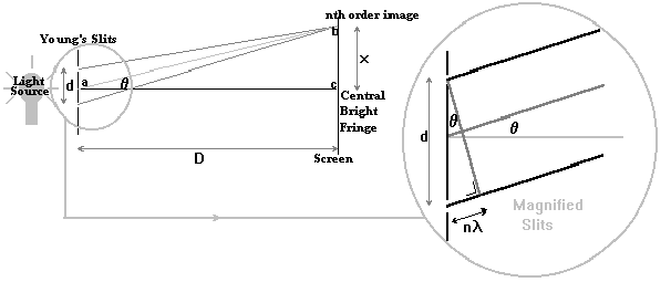
In the diagram, d is the distance between the slits, D is the distance from the screen to the slits, (N.B. D>>d), and x is the distance from the central bright fringe to the nth order image.
l is the wavelength of the (monochromatic) light source.In order to form a bright fringe; the difference in the distances travelled by the two waves (the path difference) from the slits must be equal to a whole number (n) of wavelengths (or an even number of half wavelengths). This is the condition for (maximum) constructive interference. A dark fringe is formed when the path difference is an odd number of half wavelengths; this is the condition for (total) destructive interference.

It is important to note that the distance D is much greater than d and this condition implies that when examining the circled area in the diagram (magnified slits) the lines leaving the slits are to all intents and purposes parallel to each other. This approximation can be made even more accurate by reducing d, a condition used in the diffraction grating.
The difference in the paths, as said above, must be a whole number of wavelengths for a bright fringe. This is shown above in the magnified diagram and written as n
l. The angles that these parallel lines make with the horizontal is q. From the magnified diagram, we see that;dsin
q = nl. ....(i)This equation can be used to find the wavelength of light, when using Young's Slits (or the diffraction grating) and a spectrometer.
When using the screen as above and Young's slits, the images of the slits are close together and as D is very large, the length ab is taken to be the same as the length ac.
For this reason the
![]()
i.e.
![]() ...(ii)
...(ii)
From (i) and (ii)
![]() ...(iv).
...(iv).