AXIM to Garmin Cable.
Introduction
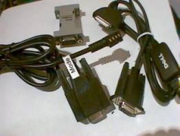
Initally I just wanted to connect my Axim to my Garmin Etrex Vista. I started with a DELL Serial Sync cable, a null model and the serial cable I got with my Etrex Vista. I soon realized that this arrangement required a modification to the DELL cable to enable the RS232 line drivers in the little box about 15cm from the AXIM. This is discussed at length on other sites.
http://ourworld.compuserve.com/homepages/bevhoward/Serial.htm
Modifing the Dell cable
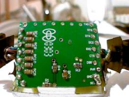
This is a very simple modification for any body able to handle a soldering iron. You just need to add a solder blob between the pin marked SEL and the pin mark GND on the back side of the PCB at the AXIM end of the board.
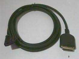
My Cable
I got fed up of this arrangement very quickly due to the sheer bulk of the cables and set out to buy a cable on-line. Initially they seemed expensive and then I realized that they were still unavailable. So I set about putting my own together.
If you want to make your own this what you need.
BOM
1. AXIM connector - Available from Gomadic, very reasonably priced and they deliver worldwide - http://www.gomadic.com/deaxcoplas.html
2. Garmin Connector - Available from pFranc, again reasonably priced and they have agent all over - http://pfranc.com/
3. Max 3232 - RS232 line driver, available from your local electronics store, should be 14 DIP
4. 0.1uF Caps by 5 - Available from your local electronics store, these should be 1206 SMT type
5. Length of 4 core cable - I’ve made a cable up to 8 meters but RS232 should work over longer distances.
6. F-15 Shrink wrap
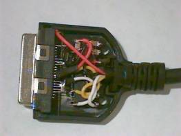
The Guts
The AXIM connector assembly is large enough to house the Max3232 circuit if you are tidy. I was able to do this by snipping the pins of the Max3232 so that they were just long enough to be able to solder the capacitors to the pins. It is also a good idea to cut away the unused pins on the AXIM connector, this allows more room to get at the pins that are actually used. If you prefer you can pull the unused pins out of the connector. This approach is more tidy but the connection to the AXIM isn’t as stiff. It’s not a good idea the remove the pins and then re-insert them as the connection is never quite the same afterwards.
Adding Power to the Cable
I have also detailed the 5 pins used to supply power to the axim for charging ie top-row pins 3, 4, 5, 6, 7. I found that the easiest way to join the pins together was to wrap a few strand of wire around the 5 pins and the tin them with solder. I took a similar approach for the ground pins.
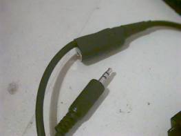
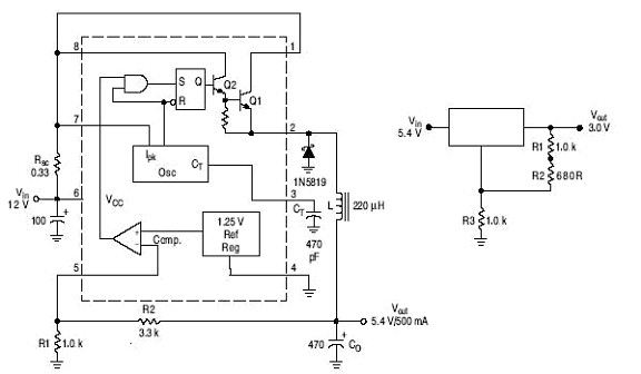
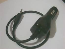
I later added a 3.5mm in line stereo socket. I Split red wire as it happens and connected the AXIM side to tip connector, the GARMIN side to the middle connector and the ground to the shaft connector. I made a car adapter by modifying a Mobile Phone type charger. These devices are very cheap and are normally based on the MC34043 which can be modified to supply 5.4V by changing the 2 control resistors that voltage divide the output into pin 5 to values like 1.0K and 3.3k. There is also usually enough room for a linear regulator like the LM317 that can be adjusted to supply 3.0 V off the 5.4V to the GARMIN.
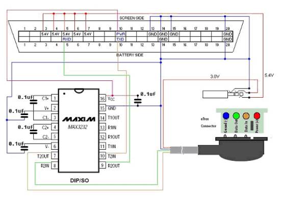
The Schematics
The schematic details the arrangement I used for my design.
The Axim supplies power to the Max3232 at about 3 to 3.4 volts. The Max3232 then used charge pump technology to convert the LVTTL siganals at 0 to 3.3V to RS232 levels at +/- 7.0V or so.
The gnd must be continuous between the 3 elements for the RS232 to work.
Pins top 13 and 14 are Select pins into the AXIM that enable the AXIM’s serial port when tied low.
Make sure you don’t wire the power pins of the AXIM to the power pins of the GARMIN.