The Voting Paper
Model
The reason we decided to do the voting paper was because in America they had
problems in voting. They complained that they made mistakes and they were not
able to have a second chance. The problem was mostly in Florida, they said that
the holes were too close to each other.
We have decided to make a model to give them a second chance. We needed three
RCXs, 5 touch sensors, 4 light sensors, 3 slow motors, 1 medium motor and 4
lights. We had it divided into 2 separate parts.
The first part has a frame to put the voting paper in. The voting paper has
six holes in all. Three for the first vote and if you want to change your mind
you punch the change of mind hole and then punch one of the holes on the second
row.
The second part is the part which registers who you voted for. When you put
the card into the machine the frame moves in with the motor until it hits the
first touch sensor the frame stops.
Then the light sensor checks the change of mind holes to check if you wanted
to change your mind. If you did change your mind it would look with the three
light sensors at the three second choice holes and register who you voted for.
If you didnt change your mind the frame would move forward until it hit the
second touch sensor. When it did the same three light sensors would look at
the first choice holes and register who you voted for.
The project worked fine but we were not able to register a spoiled vote. We
had programmed it to register a spoiled vote but it didnt work so our next
problem is to make it work.
[Top of page]
 |
|
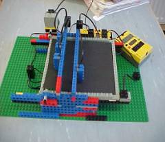
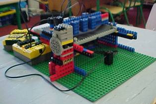
This is the Voting Tray. The Voting Paper moves forward
towards the Light Sensors on a tray driven by rack gears. There are four
light sensors. The first one, on the right, detects if the change of mind
spot has been punched. If it has it sends a signal for the other light
sensors to check which candidate has been selected in the change of mind
column. If there is no hole in the change of mind spot the tray moves
forward again until the vote column is under the three light sensors.
The light sensors do a check and choose and signal to the third RCX showing
which candidate got the vote.
|
[Top of page]
 |
|
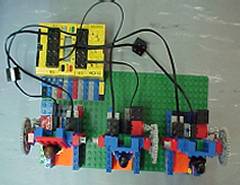
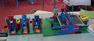
This is a view of the candidates from above. Each
candidate is run by a motor. When the RCX gets a signal that one of the
candidates has a vote, the motor turns on and the candidate stands up.
The motor remains running until the candidate hits a touch sensor and
stops.
|
[Top of page]
|
|
|
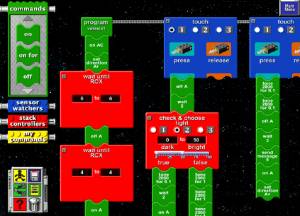
This is part of the Program for RCX 1.
|
[Top of page]
 |
|
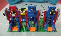
This show the three candidates. When the light sensors
on the voting tray detect a vote a numeric signal is sent to this RCX.
The RCX is programmed to activate one of the small motors operating the
three candidates, depending on the value of the signal. To register a
vote the candidate is rotated into an upright position. The rotation is
stopped by a touch sensor at the rear of each.
|
[Top of page]
 |
|
Voting Tray showing the motor mounted at the side
of the tray to operate the tray.
|
[Top of page]
 |
|
On the left is the unit which holds the three candidates.
The RCX behind it receives a numeric signal from an RCX on the voting
tray unit. The signal triggers a program which turns on a motor on the
corresponding candidate. This rotates the candidate into an upright position
to register the vote.
|
By: Peter, Ethan, Róisín, Sharon, Jane.
[Top of page]
Return
to Projects and Robots
Return
to Young Scientist Exhibition