DISCLAIMER
Connecting selfmade electronics to your computer can cause permament damage to your hardware! I am in no way responsible for any harm or damage to your hardware or loss of data as a result of following the instructions below!
Skills needed
Note that this is a guide of assembly. I assume that you are reading this because pure software "solutions" (as the "Setup Guide: Using your 3-axis wheel in GP3") couldn't solve your problem. To assemble the hardware part described here you will need basic skills in soldering electronics. However, profound skills in electronics are not required.
Analogue vs. digital controllers
This guide was developped for anlogue wheels only. Digital controllers, as the Microsoft Force Feedback Wheel, need specific drivers to work with Windows. Due to the circuit introduced below is analogue it could even damage your digital controller!
Making a 4-axis wheel
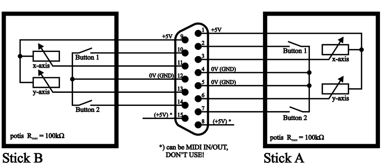
Firstly, you have to find out what axes your wheel uses. Calibrate the wheel in an other (racing) game or run my joystick detection utility JDetect. WRITE YOUR WHEEL'S CONFIGURATION DOWN AND CHECK IT TWICE ;-) The 'missing' axis will be generated by insering an adapter between the wheel's and the computer's game connectors. Ok, here is the game port's map:
| Pin | Description | |  |
| 1: | +5V |
| 2: | Button A1 |
| 3: | x-Axis A |
| 4: | 0V (GND) |
| 5: | 0V (GND) |
| 6: | y-Axis A |
| 7: | Button A2 |
| 8: | (+5V) *) |
| 9: | +5V |
| 10: | Button B1 |
| 11: | x-Axis B |
| 12: | 0V (GND) |
| 13: | y-Axis B |
| 14: | Button B2 |
| 15: | (+5V) *) |
*) Can be MIDI IN/OUT, better don't use!
The potis of the four axes have to be connected to +5V - for stick A's axes preferably pin 1, for stick B's axes preferably pin 9. Each of the potis should have a maximum resistivity of 100kW.
The switches of the four buttons have to be connected to 0V - for stick A's buttons preferably pin 4 AND pin 5, for stick B's buttons preferably pin 12.
Axis missing?
Well, depending on what axis is missing you have to connect a resistor - I recommend 47kW (that's about 100kW/2) - to the pins described in the following table.
| axis needed | connect resistor to |
| x-axis stick A | pin 1 and pin 3 |
| y-axis stick A | pin 1 and pin 6 |
| x-axis stick B | pin 9 and pin 11 |
| y-axis stick B | pin 9 and pin 13 |
Suppose your wheel lacks of stick B's y-axis. So you'll create an adapter connecting each pin of the wheel to the computer execept of pin 13. The 47kW resistor is connected to pin 13 and pin 9.

Assembling the adapter
You'll need these components:
- 1 SUB-D plug, 15 pins, male, not "90°-version" (you won't sloder it on a board) + case
- 1 SUB-D plug, 15 pins, female, not "90°-version" (you won't sloder it on a board) + case
- 1 resistor, 47kOhm
- some wire (low voltage, about 0.4mm^2, even thinner will be ok)
Follow the steps below to assemble your adapter:
- Open the SUB-D cases and put their "rear ends" together.
- Insert the SUB-D plugs in the cases.
- Solder wires and the resistor to the appropriate pins (see schematic/table above). The resistor has to be soldered to the male connector!
- Close the cases and fix them eg. with adhesive tape.
The result can look like this:

What is left to do? Plug the adapter between your wheel's and your computer's game connectors. Calibrate the wheel considering the "Setup Guide: Using your 3-axis wheel in GP3". Have fun!
Oliver Steinmetz aka Lord Vader


