Buy PCB
10 Available
€7.99

Buy PCB
10 Available
€7.99

Buy Kit
2 Available
€19.99
Buy Assembled Board
2 Available
€27.99
RS485 Relay Raspberry pi

Download Build manual Build Manual.pdf
After building up the Iso RS485/422 adapter, I figured I needed to do a project that used RS485 loopback tests can only keep you amused for so long... So here is an RS485 relay controller using the PIC16F628A that can be controlled using serial commands from cron to switch devices on and off at predetermined time
Hardware
The hardware design is shown in the schematic below:-
Power is supplied via the the connector J1 and into a 7805 linear regulator to supply 5V to the circuit and the PIC micro controller. The PIC16F628A is run off an 1.8432 Mhz crystal in order to give direct integer divider for baud rates.
The RS485 node address is set via a 5 way DIP switch DSW1 that is pulled up internally by port B this gives 32 possible addresses . A standard RS485 converter is connected to the UART pins and direction is controlled by the DE/RE signal.
At the last node on the network then J3 should be fitted to terminate the RS485 network. The Relay is driven by the RLY1 signal via Q1.
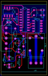
The layout is on a two layer PCB that fits into an open
enclosure that can be fitted on a DIN rail module
from pheonix contact shown here
http://www.farnell.com/datasheets/99364.pdf
This allows multiple PCB’s to be put in one enclosure.
The bill of materials for this project is
QTY PART-REFS VALUE
Resistors
---------
2 R1,R2 1k (May need to reduce to 560 for the Relay drive)
1 R3 10k
1 R4 120
Capacitors
----------
2 C1,C2 220p
2 C3,C4 47uF
Integrated Circuits
-------------------
1 U1 PIC16F628A
1 U2 78L05
1 U3 MAX487
Transistors
-----------
1 Q1 BC549BP
Diodes
------
2 D1,D3 1N4001
1 D2 LED
Miscellaneous
-------------
1 DSW1 DIPSW_5
1 J1 TBLOCK-I5
1 J2 TBLOCK-I3
1 J3 CONN-H2
1 RL1 G5CLE-1-DC5
The Protocol
For this initial network we’ll use a simple ASCII proprietary protocol as follows each command is 5 characters structured as below:
$AACMx
$ is the start of packet character
AA is the address in ASCII for example $01 would access node 1
CM is the command initially 2 commands are supported
ON= Turns relay on
OF= Turns relay off
x is the number of the relay on the board
So to turn on the relay at address 22 the command would be $22ON1 and to turn it off would be $22OF1 note no return character is sent after the command.
The code is set up to run at 19K2 baud 8N1 as default.
The PIC code
The code is written in Hitech C and uses the onboard USART with an RX interrupt routine. The code now includes timeout and corrects a previous error where I had config set up to run from the internal oscillator rather than external oscillator.
The Address is read from the external DIP switch
/**********************************************************
*RS485 Node Software
*Copyright (c) Nigel Brooke 2013
*Processor=16F628A
*Crystal Frequency = 1.8432 MHz
***********************************************************/
#include <stdio.h>
#include <htc.h>
#include "string.h"
#include <pic16f628a.h>
#define DE RB0
#define RELAY RA0
#define _XTAL_FREQ 1843200
#define SER_BUFFER_SIZE 8
#define RX_PIN TRISB1
#define TX_PIN TRISB2
#if NINE == 1
#define NINE_BITS 0x40
#else
#define NINE_BITS 0
#endif
#define SPEED 0x4
#define SER_FIFO_MASK (SER_BUFFER_SIZE-1)
__CONFIG (0x3D21); //Note make sure to check this is set up for XT Oscillator
const char* Relayon[]=
{
"$00ON1","$01ON1","$02ON1","$03ON1","$04ON1","$05ON1","$06ON1","$07ON1","$08ON1","$09ON1","$10ON1","$11ON1","$12ON1","$13ON1","$14ON1","$15ON1","$16ON1","$17ON1","$18ON1","$19ON1","$20ON1","$21ON1","$22ON1","$23ON1","$24ON1","$25ON1","$26ON1","$27ON1","$28ON1","$29ON1","$30ON1","$31ON1","$32ON1",
};
const char* Relayoff[]=
{
"$00OF1","$01OF1","$02OF1","$03OF1","$04OF1","$05OF1","$06OF1","$07OF1","$08OF1","$09OF1","$10OF1","$11OF1","$12OF1","$13OF1","$14OF1","$15OF1","$16OF1","$17OF1","$18OF1","$19OF1","$20OF1","$21OF1","$22OF1","$23OF1","$24OF1","$25OF1","$26OF1","$27OF1","$28OF1","$29OF1","$30OF1","$31OF1","$32OF1",
};
unsigned char rxfifo[SER_BUFFER_SIZE];
volatile unsigned char rxiptr, rxoptr, Addptr,Timeout;
unsigned char input;
void interrupt ISR()
{
if (T0IF)
{
Timeout--;
if(Timeout == 0)
{
Timeout = 8;
rxiptr = 0;
}
T0IF = 0;
TMR0=0;
}
while(RCIF)
{
TMR0 = 0;
Timeout = 8; //Set for around 1 second timeout
input = getch(); // read a response from the user*/
if (input == '$') //Look for the beginning of packet
{
rxiptr = 0; //If the beginning then reset the pointer
}
rxfifo[rxiptr] = input;
rxiptr++;
}
if(OERR)
{
CREN = 0;
CREN = 1;
}
}
init_comms()
{
RX_PIN = 1;
TX_PIN = 1;
SPBRG = 5;
RCSTA = (NINE_BITS|0x90);
TXSTA = (SPEED|NINE_BITS|0x20);
}
void main(void){
/*Set up Ports*/
OPTION_REG = 0b01010111;
CMCON=0B00000111;
TRISA=0B11111110;
TRISB=0B11111110;
RCIE = 1;
T0IE = 1; /* Enable peripheral interrupts */
PSA = 0;
PEIE = 1;
GIE = 1; /* Enable global interrupts */
TRISA=0B11110000; //Setup Port A Registers
TRISB=0B11111110; //Setup Port B Registers
RELAY = 0; //Set Relay to Off
init_comms(); // set up the USART - settings defined in usart.h
DE = 0;
rxiptr = 0;
Timeout = 8;
while(1){
Addptr = PORTB >>3 &0b00011111;
if (rxiptr == 6) //wait until 6 characters have been received into buffer
{
if(strncmp(rxfifo,Relayon[Addptr],6) == 0)
{
RELAY = 1;
}
else if (strncmp(rxfifo,Relayoff[Addptr],6) == 0)
{
RELAY = 0;
}
rxiptr = 0;
}
}
}
Running from the Raspberry pi
With a simple piece of python code below the relay can be switched on at the adress set by the DIP switch. To switch the relay off just change the command to OF.
If these are written as separate functions then these can be called from CRON to make a simple scheduler.
#!/user/bin/env python
import serial
import datetime
from time import sleep
ser = serial.Serial("/dev/ttyAMA0",baudrate=19200,parity=serial.PARITY_NONE,stopbits=serial.STOPBITS_ONE,bytesize=serial.EIGHTBITS )
ser.open
ser.write('$')
sleep(0.1)
ser.write('2')
sleep(0.1)
ser.write('4')
sleep(0.1)
ser.write('O')
sleep(0.1)
ser.write('N')
sleep(0.1)
ser.write('1')
sleep(0.1)
print "Relay On"
ser.close()
Running from Crontab
Now we have a program to switch the relay on and off we can set up a crontab schedule to automate the relays to switch on and off at various times during the day.
To edit the crontab first make sure it is installed apt-get install crontab
Then to edit the crontab type crontab -e
at the terminal window.
For example the command
01 22 * * * python /home/pi/Relayon1.py
will switch on relay 1 at 22:01 every day and the command
40 23 * * * python /home/pi/Relayoff1.py
will turn the same relay off at 23:40 each day.
Below is an example of my current crontab
# m h dom mon dow command
15 15 * * * python /home/pi/Relayon1.py
20 15 * * * python /home/pi/Relayoff1.py
40 23 * * * python /home/pi/Relayoff1.py
01 22 * * * python /home/pi/Relayon1.py
30 6 * * * python /home/pi/Relayon1.py
30 7 * * * python /home/pi/Relayoff1.py
36 15 * * * python /home/pi/Relayon2.py
56 15 * * * python /home/pi/Relayoff2.py
Connecting up a RS485 networked relay to the raspberry pi