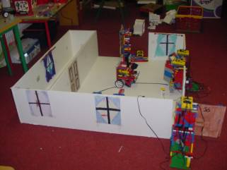
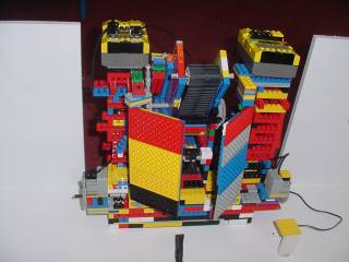
This is the house with windows
and doors and the owner inside.
Mi Future
This project is based on a story called It Wasnt Me, which we wrote for a short film which the class made before Christmas. We wrote a script, made a story-board, made a set and cast the film.
Then we filmed it and we edited the film.
Then we decided to try to make Lego robots and programme them to act out part of the story. We built and decorated the house. When we got the robots working we filmed them acting out the story. We edited the film and put music to it. We called it "Who's in the House?"
|
This film is also part of
our Mi World project. In this project we used this film as our idea of
what life might be like in the future, when many things will be controlled
by robots. We called it "Mi Future".
|
This film is also part of our Mi World project. In this project we used this film as our idea of what life might be like in the future, when many things will be controlled by robots. We called it "Mi Future"
|
|
This is the house with windows
and doors and the owner inside.
|
In our project we have the Owner of the house; we have the Robber and we have two doors and a cabinet where the jewellery is kept. All these are controlled by RCXs that are programmed to work with each other.
The Story
The Owner of the house leaves the house, and closes the door behind her. When she has left the Robber arrives and breaks into the house. He finds his way to where the jewellery is kept and manages to steal it. Then the Owner returns home to find the Robber in the house. When the Robber discovers that the Owner has arrived he makes his escape out the back door of the house.
We also made doors, windows, curtains, pictures for the walls and furniture for the house.
 |
|
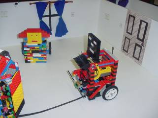
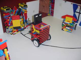
This is the inside of the house
with the owner in the background and the robber on the right. The owner
returns and the robber begins to make his getaway.
|
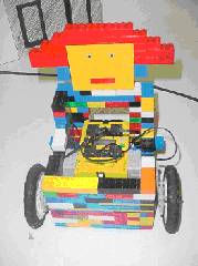
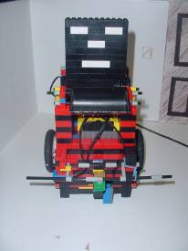
The Owner
Building
We started with the frame, which we built mostly of ordinary bricks and beams. Then we built the base out of beams. We put in a motor on each side and built them into the sides to make sure the motors stayed in place. We put in some flats to make the gearing easier. Then we started gearing. There is a 8-tooth gear on the motor and this is connected to a 40-tooth gear. On the same axle as the 40-tooth gear is an 8-tooth gear and this is connected to another 40-tooth gear. This axle also has the wheel on it. So we have a gear reduction of 5 X 5, which is 25 to 1.
This makes the model move slowly and smoothly. The gears are the same on both sides.
We built in the motors with flats and put sliders on the front. We made room for the RCX inside the model and left a gap at the front so that the RCX could send and receive signals.
 |
|
The Owner from behind. She has eyes in the back of her head. But even that is not enough. |
What it does
The Owner leaves the house and signals to the door to open on its way out. Then it turns back to the door when it has gone outside, and signals to the door to close. It then turns around and moves off.
Later the Owner comes back to the house and signals for the door to open. When the door is open the Owner goes inside and turns back and signals the door to close. When the door is closed it turns in to look around the house.
It sees the Robber and sends the signal which gets the robber to leave.
Programming
The Owner runs two programs, one for leaving the house and another for entering the house.
For leaving the house the owner is programmed to send a signal to the RCX on the door. It sends No. 1. this is the signal for the door to open. The Owner then waits for 32 seconds, which is how long the door takes to open. The Owner then moves forward Motors A & C are turned on.
When the Owner passes through the door a light sensor on the side spots a light outside the door. This is programmed to stop the motors. Then it turns on one motor going forward and the other going backwards to turn the model around 180 degrees. This takes 8.5 seconds. It sends signal No. 2 to the door RCX and this closes the door.
The Owner again is programmed to wait for the door to close. Then it turns another 180 degrees and moves off away from the house. For coming back into the house it does much the same thing until the door is closed. Then the Owner turns into the house (90 degrees), screams and sends the message that sends the robber out of the house. The message is No. 5.
 |
|
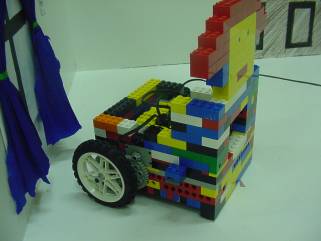
The owner. Sideview.
|
Problems
We had to make many changes since we started. The back and front of the model were not steady and kept breaking. We had to rebuild them and link the blocks into the side walls to make them stronger. The biggest problem was the programming. We had to send messages and measure how much time to wait for the door to open and measure how much time it would take to get past the door before it needed to turn.
The problem was that we were testing on the desk and the carpet of the classroom. But when the house was made we were running the models on timber, which had been painted. The model ran slower on this and sometimes it slipped. We had to keep changing the times.
By:
Laura, Deirdre, Máire Eilish, Simon, Niall and Andrew, Ciara.
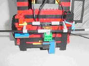
The Robber
Building
We built the Robber all black and red to make it look like a baddie. At first we built it too big so we took it apart and rebuilt it. Then we put the gears on but they didnt work very well so we had to take them off and copy the way the gears on the Owner were built.
The Robber has two motors, one driving each wheel at the back and two sliders at the front.
The gearing is the same as on the owner.
 |
|
The Robber. Front view.
|
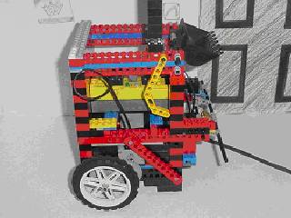
It has two light sensors, one near the ground and the other pointing out to the right hand side. The first light sensor is to get the robber to follow the black line inside the house to get to the jewellery.
The second light sensor is to sense the light near the jewellery cabinet and signal it to stop.
The Robber also has a bumper at the front. This is on a spring and when it runs into a wall the bumper hits a touch sensor. We found an example in a book where the bumper would be on the touch sensor and would release it when it hit something. We couldnt get that to work. We moved the bumper so that it would press the touch sensor instead of release it and this worked.
The RCX is inside the Robber and there is a space at the front for the RCX to send and receive signals.
What it does
The Robber comes into the house. It sends a signal to the door to open. It waits while the door is opening, then it moves inside and sends a signal for the door to close. When the door is closed it moves on into the house. It keeps going until it hits the wall at the other side.
Then the bumper presses the touch sensor. This stops the motors and reverses for a couple of seconds and turns. It then goes on and meets the black line. It follows the black line to the jewellery cabinet.
It opens the cabinet, collects the jewellery in a bucket at the front, and when the Owner comes back and screams it escapes through the back door.
Programming
The programming was very complicated. First we programmed it to move forward by turning on the two motors. It moved forward for about 6 seconds and then stopped and sent the signal (No. 1) for the door to open.
Then it waited for the door to open and then moved on again far enough to get inside the door. Then it stopped and sent the signal (No. 2) for the door to close. It waited while the door closed and then moved on again.
 |
|
Robber front showing the bumper
and light sensor.
|
When it hit the wall the bumper pressed the touch sensor. The touch sensor was programmed to stop the motors, reverse both for 3 seconds and then to turn on one motor forward and the other in reverse for 2 seconds. This would turn the model to the right.
Then it was programmed to turn on both motors going forward to move the model ahead again. This would bring the model towards the black line. When the first light sensor spotted the black line it was programmed to turn off the right hand motor, turn on the left hand motor for 0.7 seconds.
This would take the model a little to the right hand side of the line. Then the left hand motor would turn off and the right hand motor would turn back on. This would bring the model back to the line. When it reached the line the program would start again and the model would keep following the line zig zagging along.
The second light sensor was pointing to the right. When it spotted the light near the jewellery cabinet it would stop both motors and send a signal ( No. 4) to the jewellery cabinet. This was the signal for the cabinet to open. It then waits 20 seconds which is long enough for the jewellery cabinet program to run. Then it reverses for 2 seconds, to leave enough room for the doors of the jewellery cabinet to close.
The Robber now needed a different program to get out of the house. When the jewellery is unloaded, we send a message from the remote control to change from program 4 to program 5.
Program 5 is waits for a signal to begin. The signal is No. 5 and it gets this from the owner when the owner comes back into the house.
When it gets the signal it reverses for 12 seconds. Then it makes a left turn by turning one motor forward and the other backward for 7 seconds. This should have it almost facing the back door. It now sends a signal to the back door (No. 8) for the door to open. Then it waits for 25 seconds to give the door time to open and then it moves ahead out the door.
If it is not going straight for the door it will hit the wall with the bumper first. This time the bumper is programmed to reverse for 2 seconds, to turn on the left motor for one second and then to turn on both motors and move ahead. This changes the direction slightly to the right. If this is not enough it will do the same again and eventually make its way out the door.
 |
|
Side view of the Robber. The
bucket at the top is intended to be his swag bag!
|
Problems
The first problem was the gearing. When we copied the gearing from the owner this solved this problem.
The next problem was the bumper. We tried the one in the book but we had to change from releasing the touch sensor to pressing it.
We had a second touch sensor to stop at the jewellery cabinet but we were having problems with several touch sensors and we changed to a light sensor.
We had problems with the model moving on the timber. Sometimes it didnt run straight and it got stuck in the door. If the bumper got pressed at the door the whole program went wrong.
The only way we could solve this was to keep watching it and straighten it up if it was going crooked.
A big problem was when we needed to change to another program to go out. When we used the remote control to change the program from Program 5 to Program 4 it also changed the program of all the other RCXs that were on. They were all running on Program 5 and we changed them all to Program 4 and everything stopped.
We couldnt turn them all off because they were working at the same time.
We came up with an idea. The robber would come in using Program 4. Then we would change it to Program 5. This would not affect the other RCXs because they were already on Program 5. It would send them back to the beginning of Program 5 but this was not a problem because they were just waiting for a signal anyway.
By:
Ethan, Jamie, Nicola, Róisín, Sarah, Michael, Zephlin.
The Doors and the Jewellery Cabinet Building
The Doors
The two doors were built the same. We used the biggest Lego base we had and fixed on an axle on one side. We ran the axle through the special green bricks with the axle-shaped hole in them. This meant that when the axle turned so would the whole door.
The door had to be wide enough to allow the Owner and Robber to pass through. The door was heavy and to get it to open and close without breaking we had to get it moving slowly. The best way to do this was to slow it down with a worm gear.
The worm gear is connected to a 24-tooth gear and this gives a 24 to 1 gear reduction.
 |
|
This is the tower we built
to support the door. The RCX is at the bottom and the motor is attached
to the base beside the RCX.
|
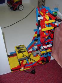
The Jewellery Cabinet
We built two high towers at each side and put a door on each side using bases as doors. The doors could open out and close back in again.
We built a kind of conveyor belt that would drop down when the doors opened. Then it would begin to spin around and this would bring out the jewels and they would fall into the bag of the robber.
We needed four motors altogether, two for the doors, one to raise and lower the conveyor belt and one to make it spin.
You can only run three motors from an RCX so we had to use two RCXs. We had to slow down the gearing on all the motors or else the doors would fall off or the conveyor belt would break.
 |
|
The Jewellery Cabinet. The
two doors are partly closed. You can see the conveyor belt in the centre
above the doors. The motors for the doors are at the bottom left and right.
The two RCXs are on top.
|
What it does
The Doors
The front door opens when the Owner or Robber, are coming in or out.
It closes when they have gone in or out.
The back door just opens when the Robber is leaving.
The Jewellery Cabinet
There is a light in front of the cabinet. This is the signal for the Robber to stop so that it is in the right place when the jewels come out of the cabinet.
The two swinging doors open to make room for the conveyor belt to drop down. The jewels are on the conveyor belt and when it begins to turn they are carried out and fall into the bag of the robber. Then the conveyor belt stops, it goes back up again and the doors close in front of it.
Programming
The Doors
The back door is programmed to wait for a signal from the robber (No. 8). Then the motor turns on. It stays opening until the door touches a touch sensor. Then it stops.
The front door is programmed to open when it gets the signal from the owner or the robber (No. 1). The motor turns on and it stays opening until the light sensor on the top of the door spots the light on the wall. Then it stops.
The signal to close is No. 2 and it stays closing until the light sensor spots the light at the top of the other wall.
It also turns on a light on the ground outside the door. This light tells the owner where to stop and turn around to send the signal to close the door.
The Jewellery Cabinet
The two RCXs are waiting for a signal from the robber (No. 4). When the robber stops it sends the signal one RCX turns on the two motors to open the doors. The motors are turned on for about 9 seconds.
The second RCX waits for this length of time and then turns on the motor to lower the conveyor belt. There is a touch sensor under the conveyor belt and when it is touched it stops the motor.
Then the second motor turns on the belt and this brings out the jewellery. The belt spins long enough for all the jewellery to be emptied. Then the motor stops and the first motor turns on again in reverse to raise up the conveyor belt again.
Meanwhile the first RCX has been waiting enough time for all this to happen, about 20 seconds, and then it turns on both motors, in reverse, to close the doors.
Problems
The Doors
The size of the doors made it difficult to get them to open and close. The worm gear helped to solve the problem. When the door opened or closed it stopped when the light sensor spotted the lights.
The problem was that when the door began to open or close the next time it spotted the light straight away and stopped.
To solve this we programmed the RCX to turn off the lights each time the door stopped. Also when the door started up the next time it waited for 6 seconds before it turned on the lights again. This gave the light sensor enough time to swing away from the lights before they came on.
Sometimes the door stopped when we didnt expect it. We discovered this was if the sun was shining in the window. It affected the light sensor as if it was seeing the lights. We stood in front of it to solve the problem!
The Jewellery Cabinet
We had loads of problems.
It was very hard to build the doors. We had to use a worm gear to turn them and they had to be built in opposite directions. It was very hard to get the housing for the worm gear to stay in its place. It is very hard to join it to other Lego pieces.
The doors were supposed to open and close until they hit touch sensors and the sensors were supposed to stop them. Several of the touch sensors didnt work. Some of them worked some of the time and not other times. We couldnt trust them.
In the end we set the doors opening and closing for so many seconds and then stopping.
Because we had four motors, lights and touch sensors to run we needed two RCXs. This meant that the two RCXs had to work together and we had to time each part of the program so that they did everything in the right order.
One of the RCXs was behind the doors so it couldnt get the signal because the doors were closed until the signal was sent. We had to put both RCXs on top of the towers so that they could get their signals.
We had to make the RCXs beep when they got the signal so that we would know if both of them picked up the signal or just one of them.
If something didnt work it was hard to figure out where the problem was because there were two RCxs and lots of wiring.
By:
Owen, Sinead, Ciarán, Roseanne, Emma, Shane, Marie, Caroline.
 |
|
The Robber has just stolen
the jewels.
|
Back to Young Scientist and Technology Exhibition