|


Author'sProjects


Sponsors


Moon Atlas has been sent to interested parties around the
world: Australia, Belgium, Canada, Denmark, France, Germany,
Greece, Hawaii, Hong Kong, Iceland, Ireland, Isle of Man, Italy,
Netherlands, New Zealand, Poland, Portugal, South Africa, Spain,
Sweden, Switzerland, UK, United Arab Emirates and the USA.
|
Shadowed Moon
Description:
The following shadow experiment was performed
using various models of craters, mountains, domes
and rilles. After each model was set down on an
adjustable table with a degree-protractor for
reading sun angles (see FIG 1), the table was then
moved through various degrees to direct sunlight
(with exception to the conic crater model), and an
overhead photograph was taken. Each adjustment was
recorded to see how the shadows behaved in
accordance with each changing sun angle.
FIG 1 - Experiment setup
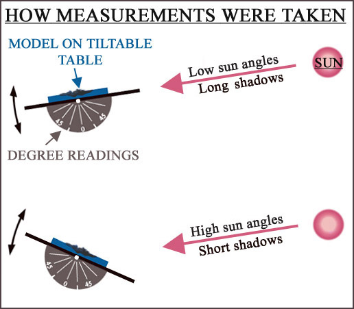
Each model was so placed initially on the table to
point directly at the Sun. The protractor reading
was set at 0 degrees to start off with, and after a
photograph was taken, the table was then adjusted to
the next degree, followed by a photograph
again...etc. Note, for each photograph, the camera
at all times remained perpendicular to the plane of
the model, and only slight adjustments of the table
horizontally rightwards had to be made to counteract
for movement of the Sun across the sky (in reality,
due to the rotation of the Earth from a Northern
Hemisphere perspective). As each model (photograph &
reading) took about an hour in length for the sun
angles covered, the horizontal movement maintained
the alignment of shadows -- from initial to final
degree reading -- looked relatively the same
throughout.
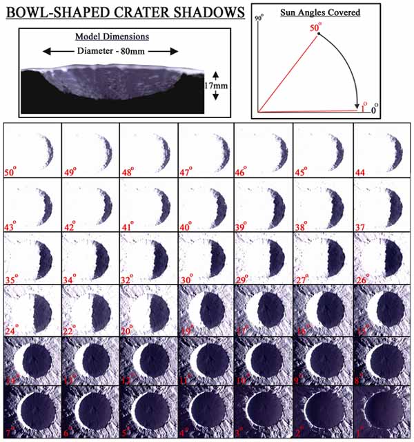
CRATERS:
Shadows in a simple bowl-shaped crater
Shadows in a conic-shaped crater
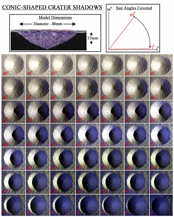
Unlike the previous bowl-shaped crater (and all
subsequent lunar features covered in this
experiment) that used direct sunlight, shadows in
the above conic-shaped crater were produced using a
simple halogen lamp. Note here that as the shadow
gets larger as lower angels are reached, the
interior of the crater receives some illumination.
This is not entirely due to internal scattering of
light from the sunlit wall of the crater, but rather
dim, ambient light scattered off the walls and
ceiling of the room in which the photos were taken.
On the Moon, however, these shadows would be totally
black, with only some back-scattering of light into
the shadows (mostly at higher sun angles) as it
reflected off, say, rocks, boulders, undulations and
dust particles from the sunlit slope side.
Shadows in a complex-shaped crater
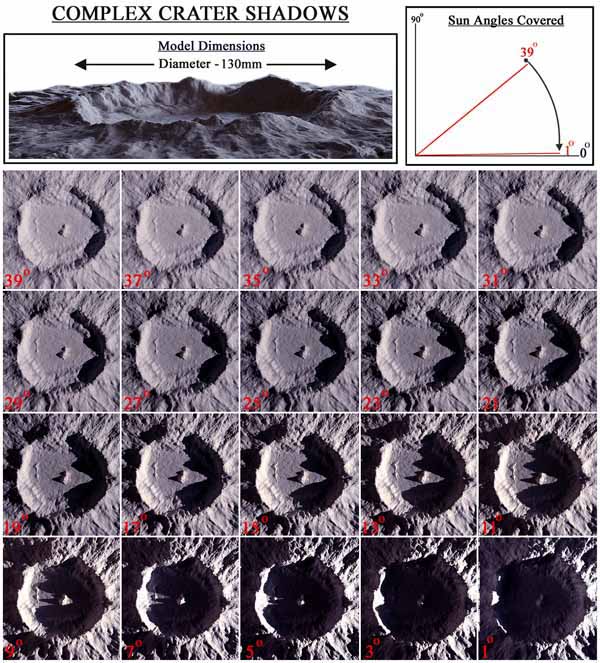
The above model was shaped so as that the
central peaks stayed in view for as long as possible
before the, somewhat, larger shadows encroached upon
them from the right. Note the tiny dot of light on
the central peak's tip (in angle 3-degrees), and how
it's shadow can just be seen on the main crater's
left ridge.
NB: For a more thorough interpretation of
shadows in craters, please see Jim Mosher's LTVT
link
here.
MOUNTAINS:
Shadows across mountains -- round, peaked and
flat

The three types of formations were chosen to
represent most mountain/peak types like seen on
the Moon. For high angles not much was happening
in terms of shadow growth, so images with angles
from 37 degrees to 25 degrees aren't shown.
These angles, however, are included in the graph
for peaks A and B, to see how the growth
progressed (note the sudden burst in shadow
growth for sun angles 10 degrees and less).
DOME:
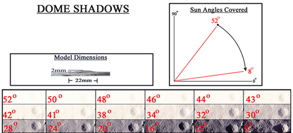
Most domes on the Moon have relatively shallow
slopes with ratios in Height (HT) to Base Diameter
(BD) starting off at around the 1:40s that climb
predominantly higher; for example, Archytas Ar 2
(56.521N, 2.71E) with HT = 275m and BD = 11000m has
a ratio of ~ 1:41, while its nearby neighbour Ar 1
(55.71N, 0.71E) with HT = 70m and BD = 33000m has a
ratio of ~ 1:470. As a result, shadows really don't
show up around domes until very low sun angles are
reached, and the dome is actually approaching very
close to, or on, the terminator itself. In the above
model the ratio is only ~ 1:11, so the shadow
appears relatively quicker than normal, however, as
the model was also built upon a curved surface to
simulate that of the moon's, the resultant setup
produced a more dramatic effect than would be
expected for a real lunar dome.
RILLES AND FAULT:
Shadows across two rille types -- linear and
sinuous, as well as a straight fault

Upto 37 images for each sun angle down to 1
degree were taken. however, as there wasn't much
change in the shadow between 33 degrees and 6
degrees (that is, from angles 32 degrees to 7
degrees), these have been left out.
|
|
|