|


Author'sProjects


Sponsors


Moon Atlas has been sent to interested parties around the
world: Australia, Belgium, Canada, Denmark, France, Germany,
Greece, Hawaii, Hong Kong, Iceland, Ireland, Isle of Man, Italy,
Netherlands, New Zealand, Poland, Portugal, South Africa, Spain,
Sweden, Switzerland, UK, United Arab Emirates and the USA.
|
WAC-ed Moon
Some of the Wide Angle Camera (WAC) views of the lunar surface as
taken by NASA's Lunar Reconnaissance Orbiter (LRO) show uncalibrated
pixels of data.
The images appear as strips of parts of a whole image that look, to
all intents and purposes, like a Venetian blind that just don't line
up correctly.
In August 2010, however, I was able to understand the effect that
was occurring with the WAC images, and this led to successful
calibration of the images
to look relatively good. The discovery was merely a
personal one from an amateur perspective as I well understood that
those engineers and scientists
working with the LRO camera data knew exactly what was happening all
the time.
However, as sometimes happens, a large divide can exist between the
amateur and professional
community, the discovery, it has to said, was well founded without their help
or assistance.
Initially, the images were manually calibrated by me - with
prospects of writing a C++ program to replace this method. However,
knowledgeable programmerswith experience much better than my limited computing
skills took on the reign in this area. And so the samples included
here (end of
page)
refer mainly to use of these programs.
Thanks then to:
Jim Mosher using
Delphi and Rick Evans using Octave
Thanks also, for their assistance in helping me to understand how
the LROC camera operations work, to:
Prof. Mark Robinson of
Arizona State University
Principal Investigator with LROC
School of Earth and Space Exploration
Tempe, AZ
Dr Jeff Anderson of the
Astrogeology Science Center
Assistant Science Center Director for Technical Operations
U.S. Geological Survey
Flagstaff, AZ

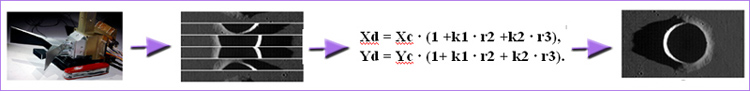
Fig 1.
On the left side of the image above you can see how the Wide Angel
Camera (WAC) onboard LRO takes sequential 'framelet' images of the
surfaceduring its orbit. Each framelet is scanned in as data by the WAC and
reversed in order, so when an uncalibrated image is viewed, it looks
exactly likethe one seen at top right of above image (here, just six framelets, 1
to 6, are shown). A better description of what is required for an
uncalibrated image into a
calibrated image can be seen in Fig 2 below. Note also that
while some of the uncalibrated images have to be rotated by 180
degrees, and then flippedhorizontally afterwards to
suit the 1961 IAU cardinal convention (for example, having North at
top and East at right as one looks at, say, the Nearside face of the
Moon),
not all images appear this way.
During periods of its orbit, the orientation viewing axis of LRO has
to be rotated because of thermal issues, so recording of images in relation to the above
cardinal convention may be correct (also, the direction
of orbit affect image recordings).
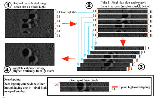
Fig 2. The above
image shows again just six set of
framelets. Each framelet in the original images (but not always) is
14 pixels high, however, if stacked in reverse order in this
configuration, features in the image won't exactly match up
correctly as
there also has to be an over-lap of 3 pixels as each framelet is
laid down (bottom of image).
When the final image has been calibrated, it still doesn't look
correct as the field of view of the WAC camera is producing
a somewhat 'squishy' effect at the side edges similar to a
bow-tie configuration. This effect can be removed by
following a formula
(below) that takes the particular pixels at the edges
and re-positioning them into the correct (and expected) location
in the final image (see
Fig 4 below)
The distortion effect has
the formula:
Xd = Xc · (1
+k1 · r2 +k2 · r3),
Yd = Yc ·
(1+ k1 · r2 + k2 · r3).
Fig 3.
The distortion formula used to correct for the 'squishy' effect seen
in some calibrated images.
For the visible detector, k is the distortion
coefficient with values of k1 = −0.0099, and
k2 = −0.00050, Xd and Yd
is the distorted position (the actual measured position in x and y),
while r is the distance from the optical centre
(the difference in samples from the optical centre). If we take the ideal camera as representing 1.0
(that is the observed expected position), then for pixels close to
the edge of the WAC photos, the exact location of these pixels are actually
closer towards the central region than one would expect. As a
result, overlap between framelets in these regions can cause problems with pixel
alignment, leading to a type of ‘jitter’ effect of features that
don’t exactly match up. Add to that, LRO may at times be flying too
fast or too slow (relative to the lunar surface) during an observing
run, so gaps in framelets where data wasn’t collected will result for the
former, while for the latter overlap will lead to duplicate data.
Gross topography over the WAC scene will also cause pixel misalignment.
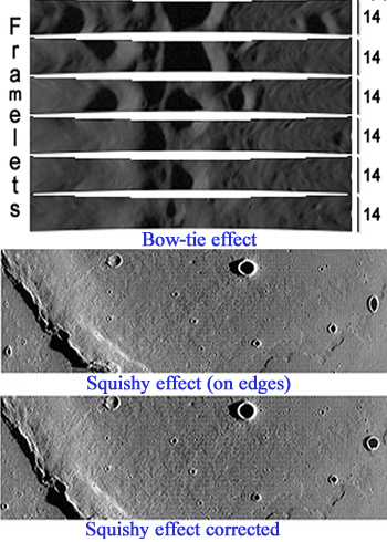
ig 4. Above image shows the
'bow-tie' effect, the 'squishy' effect and its correction.
The WAC Camera
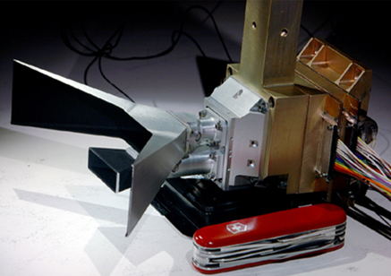
Fig 4.
The Wide Angel Camera (WAC) above is the large baffle-like appendage
attached to the main electronics system (the small baffle below it
is the UV optic).
The WAC measures 14.5 cm x 9.7 cm x 7.6 cm (note penknife as
dimension reference), and has a field-of-view (FOV) of approximately
92 degrees.
It is a pushframe camera consisting of a
multispectral imaging system that is able to collect small multiple,
sequential lines of data in one integration,
called a framelet, that are then built up as a complete image
through the downtrack motion of LRO. Image credit
Malin Space Science Systems.
Some samples (just two of hundreds already
calibrated)


Some useful references
* Robinson, M. S. et al. (2010). Lunar Reconnaissance Orbiter
Camera (LROC) Instrument overview –
http://www.springerlink.com/content/572k747286387261/fulltext.pdf
– Space Science Reviews, Volume 150, Issue 1-4, pp. 81-124, 2010.
* Chin, G.
et al. (2007). Lunar Reconnaissance Orbiter
Overview: The Instrument Suite and Mission –
http://lro.gsfc.nasa.gov/library/LRO_Space_Science_Paper.pdf
Springer Science and Business Media, Inc. 2007.
* Robonson, M. S. et al. (2005). LROC – Lunar Reconnaissance Orbiter
Camera –
http://www.lpi.usra.edu/meetings/lpsc2005/pdf/1576.pdf
Lunar and Planetary Science Conference No. 36, 2005.
|